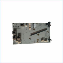
This printed circuit board serves as a bridge controller for GE Mark VIe turbine systems. It manages data exchange between multiple VME backplane segments. Therefore, it enables scalable system architecture for large turbine control applications.
Physical and Bridge Specifications
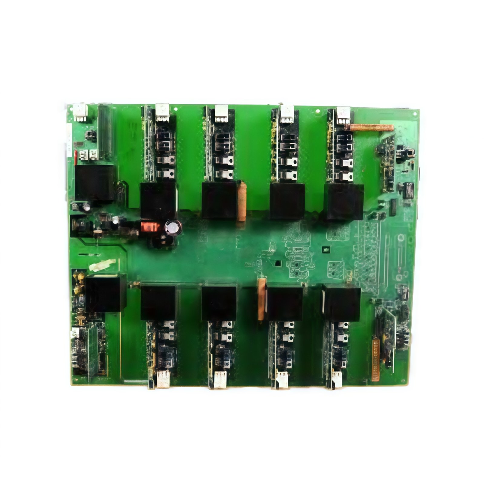
The GE IS200BCAAH1A IS200BCAAH1ABA measures 26.0 cm in length and 18.5 cm in width. Moreover, its board weight equals approximately 0.52 kg for rack mounting. Two 64-pin male connectors link this board to separate VME backplane segments. Additionally, the board includes a high-speed data routing controller.
| Parameter | Specification |
|---|---|
| Brand | General Electric (GE) |
| Full Model | IS200BCAAH1A IS200BCAAH1ABA |
| Category | Printed Circuit Board (Bridge Controller) |
| Dimensions (L x W) | 26.0 cm x 18.5 cm (10.24″ x 7.28″) |
| Board Weight | 0.52 kg (1.15 lbs) |
| Backplane Interfaces | 2 x 64-pin Male Connectors (Dual VME Segments) |
| Bridge Type | Intelligent VME-to-VME Bridge |
| Data Transfer Rate | 40 MB/s (Peak) |
| Addressable Space | 16 MB per Segment |
| Data Path Width | 32 Bits |
| Bridge Mode | Automatic or Software Configurable |
| Access Time | 150 ns (Typical) |
| On-Board Components | 1 Bridge Controller IC + 2 FPGA Chips + 4 Memory Chips + 4 Bus Transceivers + 6 Protection Diodes + 1 Oscillator (40 MHz) + 1 Voltage Regulator + 1 Temperature Sensor + 2 LED Drivers |
| Energy Storage | 2 x 100 µF Electrolytic Capacitors (35V) + 4 x 10 µF Tantalum (25V) |
| Operating Voltage | +5 VDC and +3.3 VDC from Backplane |
| Power Consumption | 4.5 W (Typical) |
| Isolation Rating | None (Direct Backplane Connection) |
| Operating Temperature | -20°C to +65°C (-4°F to +149°F) |
| Status Indicators | 2 Green LEDs (Segment A Active + Segment B Active) + 1 Green LED (Power) + 1 Yellow LED (Bridge Busy) + 1 Red LED (Fault) |
VME Bridge Controller Features
The GE IS200BCAAH1A IS200BCAAH1ABA connects two independent VME backplane segments intelligently. Specifically, the bridge controller manages data routing between up to 21 slots per segment. In addition, the 32-bit data path transfers information at 40 megabytes per second. Moreover, the bridge operates automatically or allows software configuration for special cases. Furthermore, each segment accesses 16 megabytes of addressable memory space. Consequently, this board enables large Mark VIe systems with many I/O cards.
Dual FPGA and Bridge Architecture
Two FPGA chips provide flexible data routing and protocol management. For instance, the first FPGA handles data from segment A, and the second from segment B. In addition, dedicated bus transceivers drive signals across the bridge without timing errors. Moreover, the access time of 150 nanoseconds adds minimal latency to data transfers. Thus, the bridge appears transparent to software running on either segment.
Energy Storage and Signal Integrity
This printed circuit board stores energy using six onboard capacitors for power filtering. Specifically, two electrolytic capacitors smooth the 5 VDC supply for stable bridge operation. In addition, four tantalum capacitors provide high-frequency noise suppression for the FPGAs. Furthermore, a temperature sensor monitors board ambient for derating purposes. Therefore, the GE IS200BCAAH1A IS200BCAAH1ABA maintains data integrity under heavy bus traffic.
Installation and Diagnostic Indicators
Six LED indicators provide operational status at a glance on this board. First, a green Power LED lights when the backplane supply voltages are present. Second, two green Segment Active LEDs illuminate when each VME segment is operational. Third, a yellow Bridge Busy LED flashes during active data transfer across the bridge. Finally, a red Fault LED indicates bridge configuration errors or hardware failures. Additionally, the board features four mounting holes for secure rack attachment. Thus, you can monitor bridge status instantly without external test equipment.
Details
| Weight | 0.1 kg |
|---|---|
| Dimensions | 25 × 108 × 127 mm |
Reviews
There are no reviews yet.