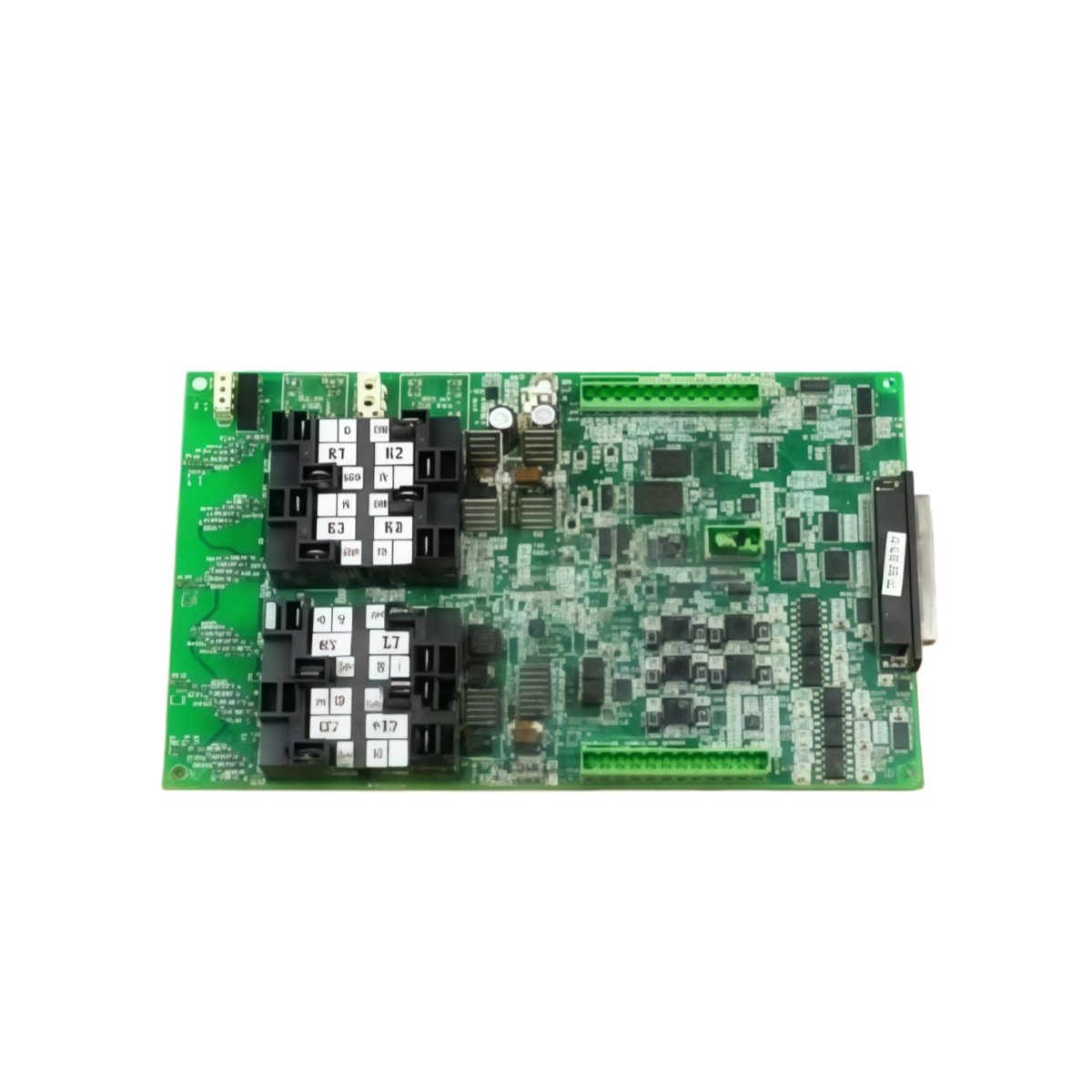
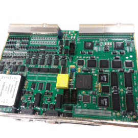
This GE IS200AEADH1A IS200AEADH1ACA Input/Output Grid Fork Module manages signal distribution for Mark VI turbine control systems. The module routes grid synchronization signals between protection relays and the main controller. You will find this component in many GE power generation applications. The IS200AEADH1ACA variant includes a rugged conformal coating for harsh environments.
Technical Specifications
| Parameter | Specification |
|---|---|
| Full Model | GE IS200AEADH1A IS200AEADH1ACA Input/Output Grid Fork Module |
| Category | Input/Output Grid Fork Module |
| Input Channels | 8 Grid Synchronization Inputs (Opto-Isolated) |
| Output Channels | 4 Relay Outputs (Form C, 5A) |
| Input Voltage Range | 24V to 250V AC or DC |
| Response Time | Less than 10 milliseconds |
| Isolation Voltage | 4000 V RMS (Input to Logic) |
| Dimensions (H x W) | 180 mm x 120 mm |
| Weight | Approximately 0.62 kg |
| Connectors | 2 x 20-Pin Headers, 1 x Terminal Block |
| Component Count | 134 Discrete Components |
| Energy Storage | 8 x 10 µF Signal Capacitors |
Grid Interface and Signal Routing Features
The GE IS200AEADH1A IS200AEADH1ACA Input/Output Grid Fork Module monitors grid voltage presence for synchronization decisions. Each input channel includes a programmable threshold for reliable detection. The board provides dry contact outputs for breaker control signals. Furthermore, it includes LED indicators for each channel’s status. Consequently, your turbine connects to the grid only when voltage conditions match safely.
Installation and Connection Steps
Mount this GE IS200AEADH1A IS200AEADH1ACA Input/Output Grid Fork Module in any Mark VI rack slot. First, connect grid voltage inputs to the terminal block securely. After that, wire the relay outputs to the breaker trip and close circuits. Then, attach the 20-pin headers to the main controller backplane. Finally, set the input thresholds using the onboard potentiometers before system startup.
Energy Discharge and Safety Notice
This GE IS200AEADH1A IS200AEADH1ACA Input/Output Grid Fork Module stores minimal energy in its capacitors. However, you must wait 30 seconds after power removal before handling. The eight signal capacitors discharge through internal resistors. Never connect grid voltages above the specified range to any input channel.
Status Indication and Diagnostics
Eight green LEDs show active grid presence on each input channel clearly. Four yellow LEDs indicate the state of each relay output. A red LED illuminates when the board detects an input wiring fault. These indicators help technicians verify grid synchronization without external test equipment.
Details
| Weight | 0.1 kg |
|---|---|
| Dimensions | 25 × 108 × 127 mm |
Reviews
There are no reviews yet.