
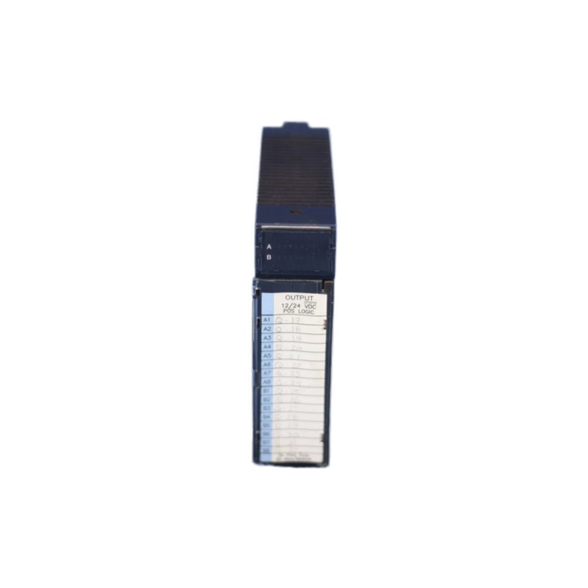
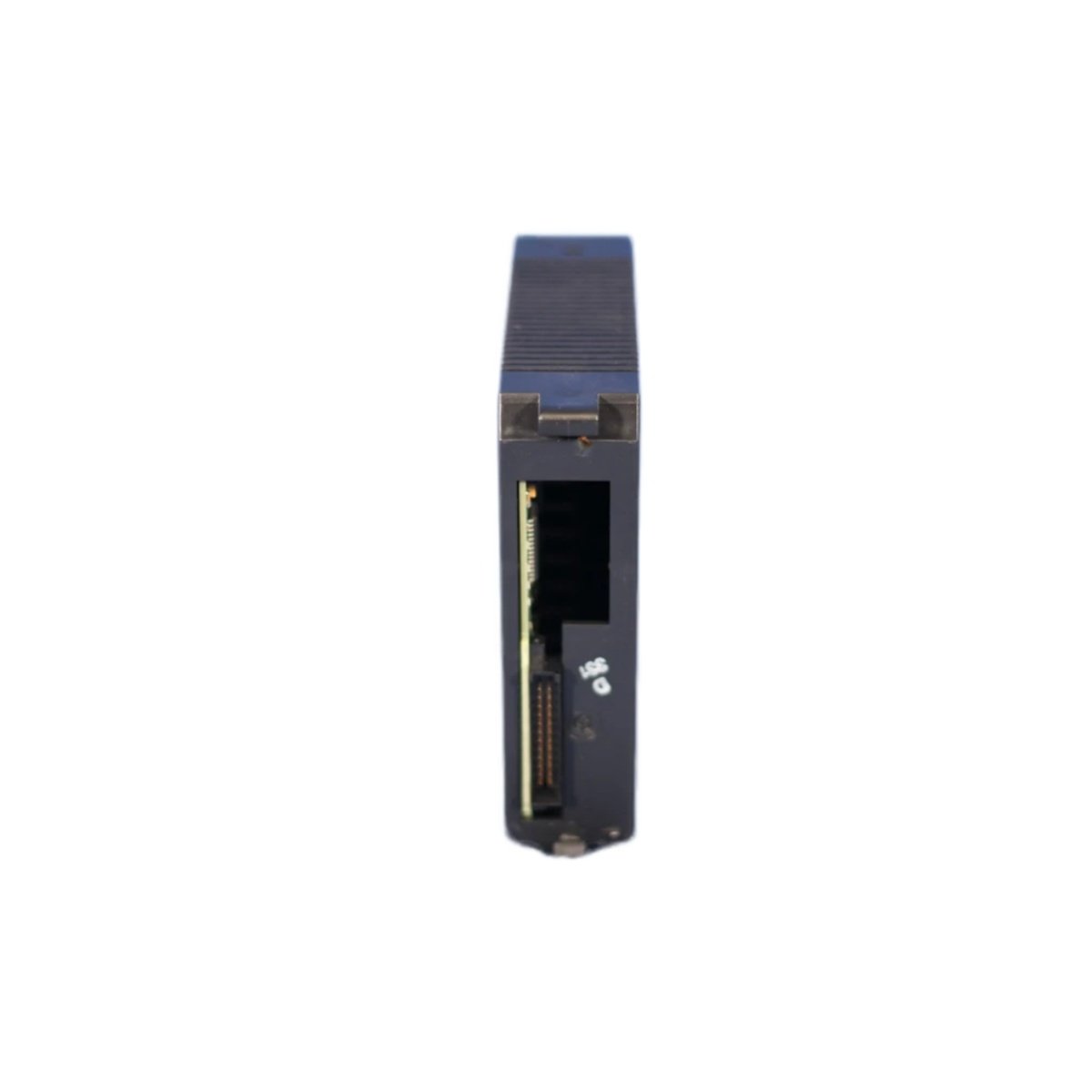
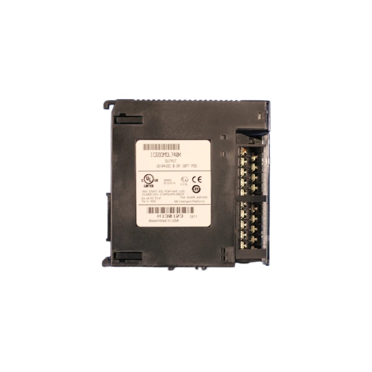
Series 90-30 Discrete Output Module
The IC693MDL740 functions as a discrete output module within the GE Series 90-30 control system. This module drives up to eight independent output channels. It connects directly to actuators, solenoids, and indicator lamps. The unit also includes protection circuitry to safeguard connected devices.
Key Technical Specifications
| Parameter | Specification |
|---|---|
| Brand | GE |
| Model | IC693MDL740 |
| Category | Discrete Output Module |
| System Compatibility | Series 90-30 PLC |
| Output Channels | Offers 8 discrete output channels |
| Output Type | Provides relay contact outputs |
| Contact Rating | Supports 2 A at 250 Vac or 30 Vdc |
| Output Voltage | Handles 24 Vdc or 120/240 Vac |
| Response Time | Delivers 10 ms nominal |
| Isolation | Offers 1500 Vac optical isolation |
| Indicators | Includes individual channel LED status |
| Power Supply | Draws +5 Vdc from the backplane |
| Backplane Current | Consumes 200 mA typical |
| Mechanical Life | Rated for 10 million operations |
| Electrical Life | Rated for 100,000 operations at rated load |
| Operating Temperature | Functions from 0°C to +60°C |
| Storage Temperature | Withstands -40°C to +85°C |
| Dimensions | Measures 125.0 mm x 64.0 mm x 80.0 mm |
| Weight | Weighs approximately 0.45 kg |
| Mounting | Plugs into Series 90-30 rack slots |
| Compliance | Meets CE, UL, and CSA standards |
Output Capabilities and Protection
This module provides eight independent relay outputs for controlling field devices. Each channel offers a Form C contact for flexible wiring arrangements. The module also includes surge suppression to protect against inductive load transients. Furthermore, it features individual channel status indicators for quick visual diagnosis. The relays provide reliable switching for both AC and DC loads.
Installation and Configuration
First, insert the IC693MDL740 into an available slot within the Series 90-30 rack. Ensure the module seats firmly into the backplane connector. Next, wire the field devices to the appropriate output terminals. After that, apply power and observe the LED status indicators. You can then configure the output mapping through the programming software.
Maintenance and Operational Reliability
This module’s relay contacts offer long service life under normal operating conditions. However, you should periodically check the output operation using the diagnostic functions. We recommend you inspect the terminal connections for tightness regularly. You should also monitor the LED indicators to confirm proper channel status.
Details
| Weight | 0.45 kg |
|---|---|
| Dimensions | 125 × 64 × 80 mm |
Reviews
There are no reviews yet.