
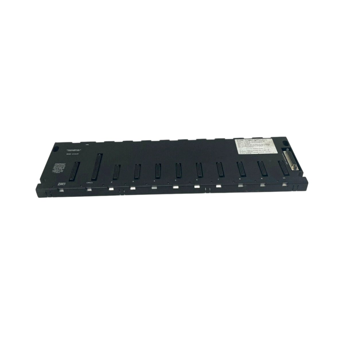
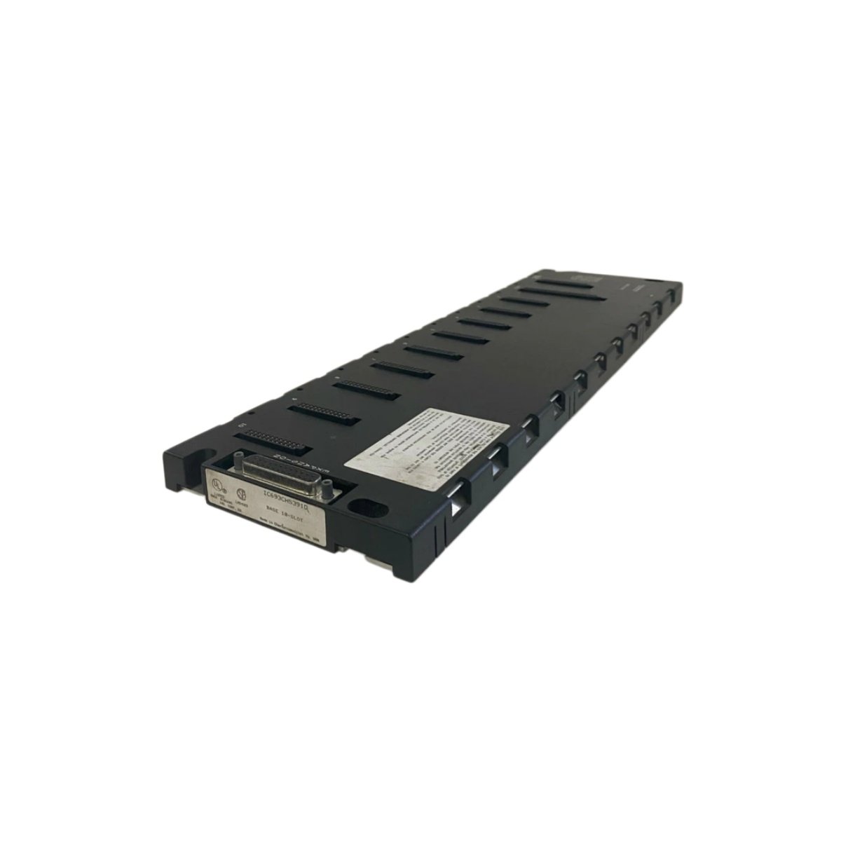
The GE IC693CHS391D base rack serves as the primary chassis for CPU and I/O modules in a Series 90-30 system. This 10-slot backplane accommodates the processor, power supply, and up to eight additional modules. Its sturdy chassis measures 270 mm in height, 445 mm in width, and 120 mm in depth.
Technical Specifications
| Parameter | Specification |
|---|---|
| Brand | GE Fanuc |
| Model | IC693CHS391D |
| Category | Base Rack / Backplane |
| Number of Slots | 10 |
| CPU Slot Position | Leftmost slot (slot 0) |
| Power Supply Slot | Rightmost slot |
| Backplane Type | Passive |
| Bus Communication | Parallel I/O bus |
| Backplane Current Capacity | 5.0 A (at 5 V DC) |
| Power Supply Interface | 1 position (right side) |
| Expansion Interface | 2 connectors (for expansion racks) |
| Maximum Expansion Cables | 2 (via ribbon connectors) |
| Dimensions (H×W×D) | 270 × 445 × 120 mm |
| Weight | 3.10 kg |
| Material | Powder-coated steel |
| Color | Beige |
| Operating Temperature | 0°C to +60°C |
| Storage Temperature | –25°C to +85°C |
| Protection Rating | IP20 |
| Mounting Type | Panel mount (screw) |
| Component Count | 1 (passive backplane PCB) |
System Architecture and Slot Configuration
The GE IC693CHS391D provides ten slots for housing the CPU, power supply, and I/O modules. Slot 0 (leftmost) accepts the Series 90-30 processor module for system control. Slot 9 (rightmost) accommodates the power supply module for distributing energy. Slots 1 through 8 accept discrete, analog, or communication modules for system customization.
Backplane Communication and Data Transfer
This rack features a passive backplane that routes signals and power between connected modules. The CPU communicates with I/O modules over this parallel backplane for deterministic updates. The backplane carries both address and data signals to ensure correct module identification. Modules respond within one scan cycle for synchronous control system operation.
Power Distribution and Current Capacity
The GE IC693CHS391D backplane distributes 5 V DC power from the power supply module. The bus supports up to 5.0 A total current draw from installed modules. This capacity accommodates typical combinations of CPU, discrete, and analog modules. The power supply connects directly to the backplane through the rightmost slot interface.
Expansion Interfaces and System Growth
This base rack includes two expansion connectors for adding remote I/O racks. The first connector links to expansion rack 1 via a shielded ribbon cable. The second connector enables daisy-chaining to expansion rack 2 or beyond. The maximum cable length to any expansion rack reaches 15.2 meters (50 feet).
Physical Construction and Panel Installation
The GE IC693CHS391D chassis uses powder-coated steel construction for industrial durability. This robust material resists corrosion and maintains structural integrity in factory environments. The beige finish matches other Series 90-30 components for uniform appearance. Mounting tabs on the top and bottom edges accept screws for secure panel attachment.
Module Insertion and Removal Procedure
Insert Series 90-30 modules into the GE IC693CHS391D by aligning with the slot guide rails. The modules lock into place with integral retaining clips for secure mechanical retention. Remove modules by pressing the retaining clip and pulling the module handle firmly. The passive backplane enables hot-swapping when using a suitable power supply configuration.
Mounting Orientation and Clearance Requirements
Mount the GE IC693CHS391D on a flat panel surface using the factory-provided mounting tabs. Use four M6 screws to secure the rack firmly to the mounting surface. Position the rack horizontally or vertically depending on cabinet space availability. Allow at least 100 mm clearance above and below the chassis for cable routing and airflow.
Details
| Weight | 0.65 kg |
|---|---|
| Dimensions | 140 × 110 × 75 mm |
Reviews
There are no reviews yet.