

Input Architecture and Field Interface
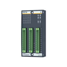
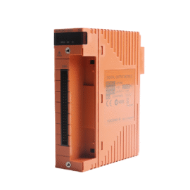
This VersaMax input module provides high-density 24 VDC signal acquisition for industrial control systems. It features 16 isolated input channels arranged in two groups of eight. Each channel accepts 24 VDC signals from pushbuttons, sensors, and limit switches. The module includes LED indicators for real-time per-channel status monitoring. Consequently, this unit serves as a reliable field interface in GE VersaMax systems.
Technical Specifications
| Parameter | Specification |
|---|---|
| Brand | GE |
| Model Number | IC200MDL640 |
| Input Channels | 16 discrete inputs |
| Input Voltage | 24 VDC nominal |
| Input Range | 18–30 VDC |
| On-State Threshold | >15 VDC |
| Off-State Threshold | <5 VDC |
| Input Current | 7 mA typical at 24 VDC |
| Input Impedance | 3.4 kΩ |
| Response Time | 1 ms typical (on/off) |
| Group Isolation | 500 VDC (group-to-group) |
| Channel Isolation | 1500 VAC to backplane |
| Current Draw | 120 mA from 5 VDC backplane |
| Power Dissipation | 3.0 W maximum |
| Operating Temperature | 0°C to +60°C |
| Storage Temperature | –40°C to +85°C |
| Humidity | 5% to 95% non-condensing |
| Dimensions (H x W x D) | 85 mm x 25 mm x 110 mm |
| Weight | 0.20 kg |
| Termination Interface | 20-pin removable terminal block |
| Wire Gauge | 16–22 AWG |
| Status Indicators | 16 green LEDs per channel |
Signal Acquisition and Input Filtering
The IC200MDL640 captures input signals with a typical response time of 1 millisecond. Each channel includes a programmable debounce filter to reject contact bounce. The filter time ranges from 0 to 100 milliseconds through software configuration. Input status data updates synchronously with the system scan cycle. This reliable acquisition supports both high-speed and general-purpose applications.
Field Wiring and Termination Design
A removable 20-pin terminal block provides convenient field wiring access. Each input channel requires two terminations: signal and common return. The module groups channels into two isolated banks of eight inputs each. A removable marker strip allows for clear channel identification. This design simplifies installation and future wiring modifications.
Power Requirements and Energy Consumption
The module draws 120 mA from the 5 VDC backplane supply. Internal circuitry maintains stable operation across the specified input voltage range. Total power dissipation reaches 3.0 W under full input load. This low consumption minimizes thermal load within the control cabinet. Consequently, users can install multiple modules without cooling concerns.
Installation and Mounting Instructions
Insert the module into any VersaMax I/O slot on the mounting rail. Press firmly until the module seats fully onto the backplane connector. Secure the module with the retaining clip mechanism provided. Wire the removable terminal block before inserting it into the module. Verify the system configuration recognizes the module automatically.
System Integration and Compatibility
This module integrates seamlessly with all VersaMax system components. It communicates with the controller through the I/O bus interface. The system software automatically assigns inputs to memory addresses. Users can mix this module with other VersaMax I/O types in the same rack. This compatibility provides flexibility in system design and expansion.
Environmental Performance and Construction
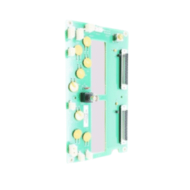
The module operates reliably in 0°C to 60°C ambient temperatures. It withstands humidity levels between 5% and 95% non-condensing. The PCB features conformal coating for moisture and dust protection. This construction ensures dependable service in typical industrial environments.
Diagnostics and Maintenance
Front-panel LEDs indicate each input’s status for quick visual verification. The controller software provides diagnostic data for troubleshooting. Replace the module if inputs fail to respond correctly. Inspect the terminal block connections periodically for tightness.
Details
| Weight | 0.2 kg |
|---|---|
| Dimensions | 85 × 25 × 110 mm |
Reviews
There are no reviews yet.