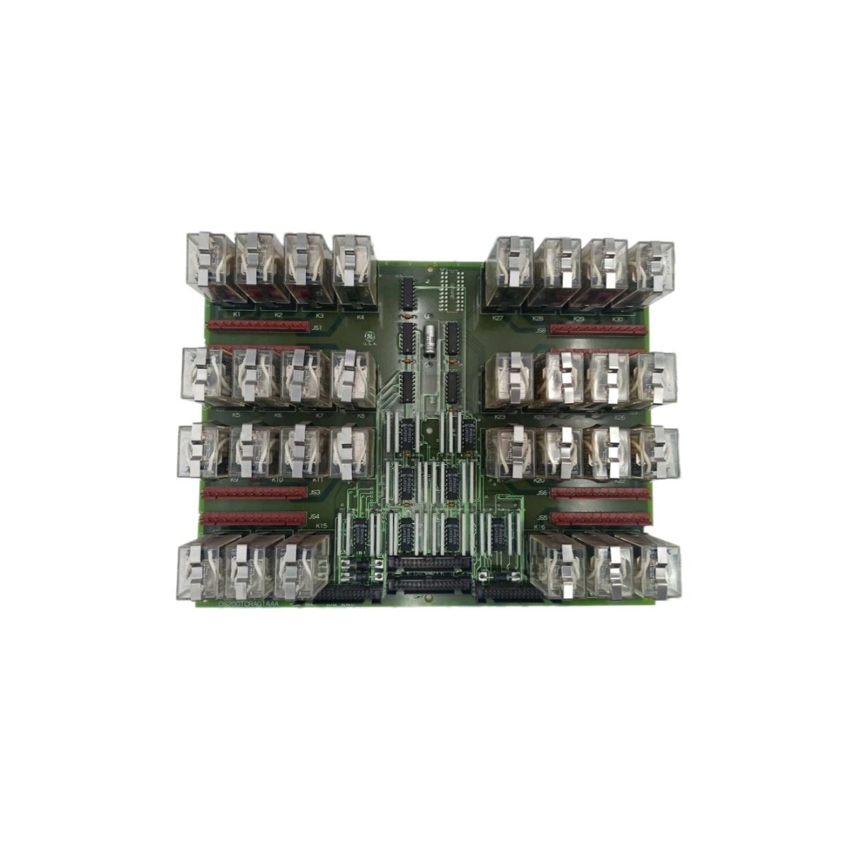
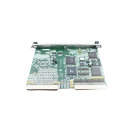
Technical Specifications and Board Design
This relay output board provides discrete switching for GE Mark V turbine control systems. The GE DS200TCRAG1A DS200TCRAG1AAA drives solenoids, contactors, and annunciator circuits reliably. You can install this board into any standard Mark V rack slot position. Its rugged construction handles continuous operation in high-temperature environments. The board weighs approximately 0.63 kilograms. Its dimensions measure 28 cm in height, 18 cm in width, and 2.5 cm in depth.
| Parameter | Specification |
|---|---|
| Brand | GE Energy / General Electric |
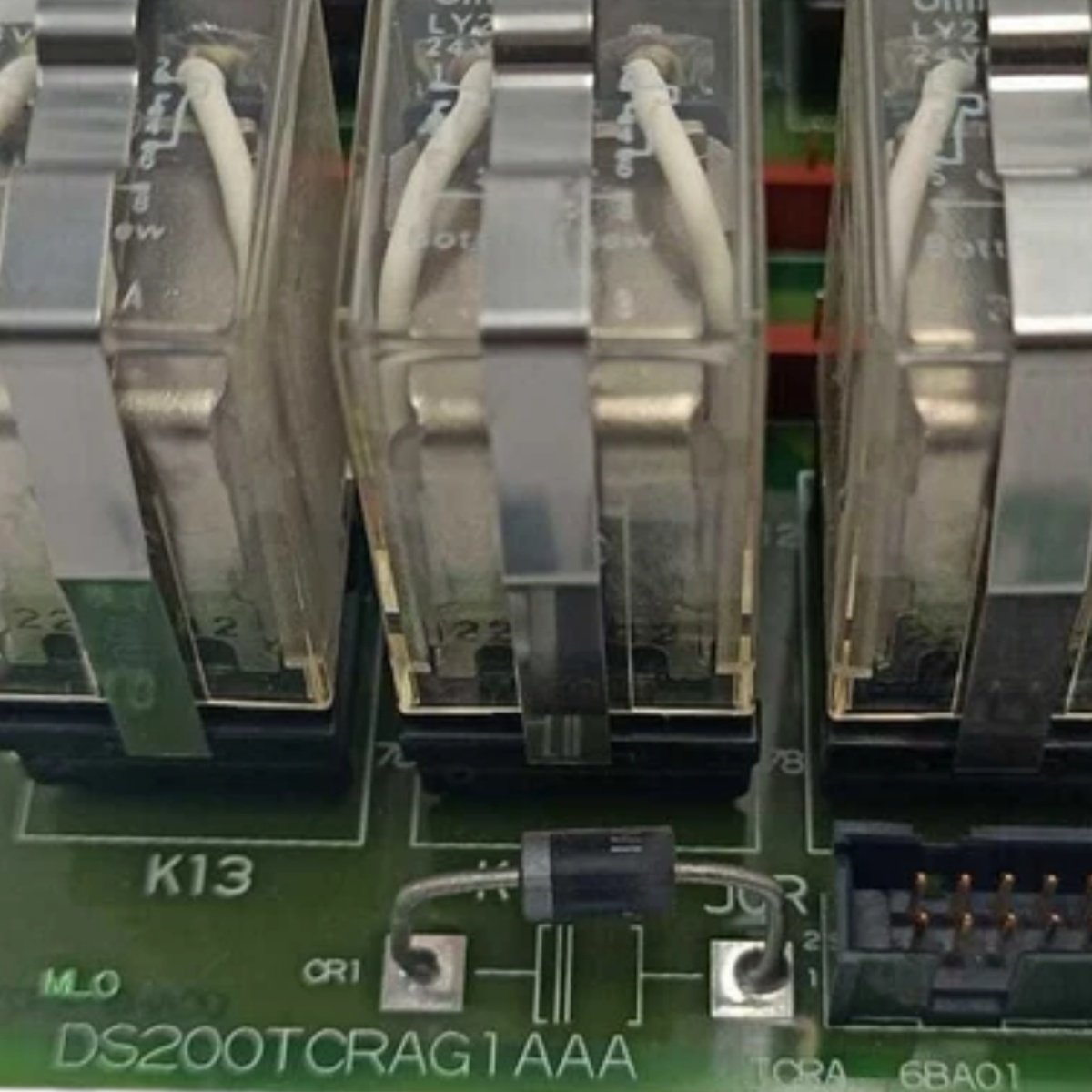
| Model | DS200TCRAG1A DS200TCRAG1AAA |
| Category | Relay Output Board / Discrete Output Card |
| Weight | 0.63 kg |
| Height | 28 cm |
| Length | 18 cm |
| Thickness | 2.5 cm |
| Number of Outputs | 12 relay outputs |
| Relay Type | Electromechanical, single-pole double-throw (SPDT) |
| Contact Rating (Resistive) | 10 Amps at 250V AC / 30V DC |
| Contact Rating (Inductive) | 5 Amps at 250V AC / 30V DC |
| Maximum Switching Voltage | 250V AC or 30V DC |
| Coil Voltage | 24V DC (from backplane) |
| Response Time (Operate) | 12 milliseconds maximum |
| Response Time (Release) | 8 milliseconds maximum |
| Mechanical Life | 20 million operations |
| Electrical Life | 200,000 operations at rated load |
| Isolation Voltage | 2000V AC between coil and contacts |
| Energy Storage | None (no battery) |
| Component Count | Single PCB with 12 relays, suppression diodes, and LED indicators |
Output Configuration and Load Control
Each of the twelve relays provides a set of changeover contacts. You can wire each output as normally open or normally closed independently. The GE DS200TCRAG1A DS200TCRAG1AAA switches resistive loads like heaters and lamps efficiently. It also handles inductive loads like turbine solenoids and brake coils. Each relay includes a built-in suppression diode across the coil. This diode prevents voltage spikes from damaging the transistor drivers. The board provides a red LED for each relay individually. This LED illuminates when the turbine controller energizes the corresponding coil.
Signal Processing and Driver Circuits
The board receives output commands from the main turbine controller via the backplane. Driver transistors amplify the logic signals to energize each relay coil. The GE DS200TCRAG1A DS200TCRAG1AAA includes optical isolation between logic and field circuits. Consequently, backplane faults cannot affect the relay outputs. The board monitors each relay’s coil for short circuit conditions. A fault detection circuit reports any driver anomalies to the controller. The board defaults all outputs to a safe de-energized state during power loss.
Installation and Operational Guidelines
You must insert this board into a dedicated slot in the Mark V rack. The backplane supplies 5V and 24V DC power to the board automatically. The GE DS200TCRAG1A DS200TCRAG1AAA draws approximately 170 mA from the 5V supply. It draws additional current based on how many relays energize simultaneously. You should verify the total load current does not exceed 10 Amps per contact. Exceeding this limit will weld the relay contacts permanently. The board requires no external battery for normal operation. You should replace the entire board if any relay fails mechanically.
Details
| Weight | 0.45 kg |
|---|---|
| Dimensions | 170 × 145 × 65 mm |
Reviews
There are no reviews yet.