
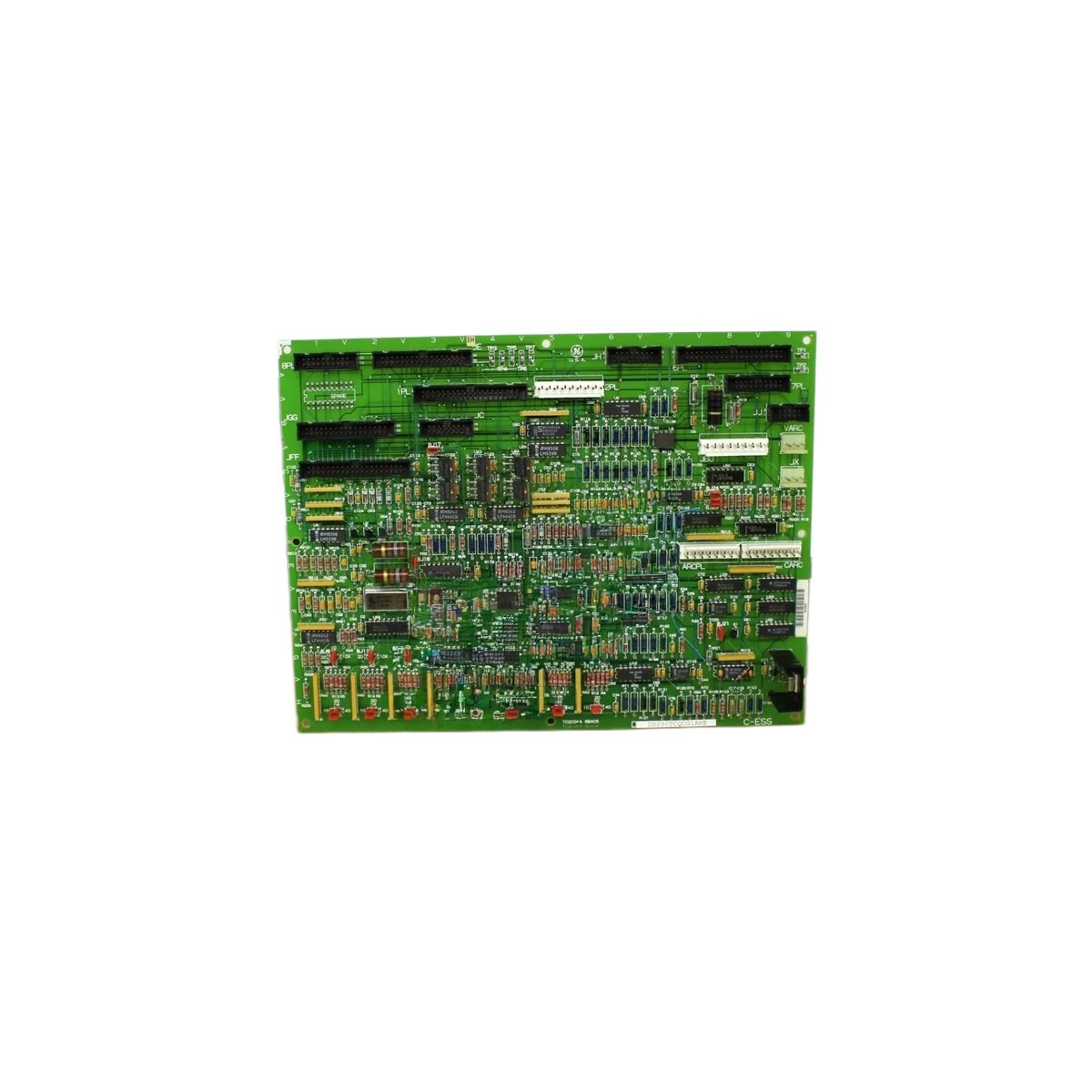
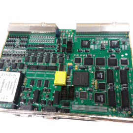
This RST overflow board handles signal routing in GE drive systems. It manages reset and timing functions for reliable system operation. The unit mounts inside the drive cabinet as a supporting component.
Technical specifications
| Parameter | Specification |
|---|---|
| Brand | GE Energy |
| Model 1 | DS200TCQCG1A |
| Model 2 | DS200TCQCG1AHE |
| Product Family | Mark V / Drive Control |
| Category | RST Overflow Board |
| PCB Layer Count | 4 layers |
| Base Material | FR-4 flame retardant |
| Component Count | Approximately 85 components |
| Integrated Circuits | 8 ICs (logic, buffers, timers) |
| Connector Types | 2 x 34-pin headers, 1 x 20-pin header |
| Power Supply | 5V DC from backplane |
| Current Consumption | 150 mA typical |
| Test Points | 6 gold-plated test points |
| Status Indicators | 2 x LEDs (PWR, ACT) |
| Dimensions (L x W) | Approx. 22 cm x 15 cm |
| Thickness | Approx. 1.6 mm |
| Weight | Approx. 0.25 kg |
| Energy Storage | 6 x electrolytic capacitors (47 µF each) |
| Operating Temperature | 0°C to 55°C |
| Mounting | 4 x screw holes (M3) |
Detailed Technical Analysis
This overflow board uses a 4-layer PCB for reliable signal routing. The inner layers provide power distribution and ground shielding for noise reduction. Approximately 85 components populate both sides of this circuit board. Eight integrated circuits handle logic buffering and timing functions.
Now let us examine its power characteristics. This board draws 150 milliamps from the 5V backplane supply. Six electrolytic capacitors filter the power input effectively. Each capacitor stores 47 microfarads of electrical charge. The board contains no batteries for energy storage.
This RST overflow board features two LED status indicators. A green PWR LED shows the 5V supply is present. A yellow ACT LED indicates normal board activity. Six gold-plated test points allow signal monitoring with an oscilloscope. The board connects to other system cards via three header connectors.
Installation and Connection Guidelines
You mount this board using four M3 screws with insulating standoffs. Ensure proper alignment before pressing connectors together. This overflow board fits into a dedicated slot in the drive rack. Use proper ESD precautions when handling this board.
Verify all cable orientations before applying power to the system. The board automatically initializes its timing circuits upon startup. This component requires no field configuration or adjustments. Always power down the drive before inserting or removing this board.
Practical Applications
Engineers use this overflow board for GE drive repair and restoration. It serves as a direct replacement for failed original boards. This component also works in legacy drive upgrade projects. Its compact design fits inside standard drive enclosures.
Summary of Features
To conclude, this RST overflow board features a 4-layer PCB and 85 components. It weighs 0.25 kilograms and draws 150 milliamps at 5V. Choose DS200TCQCG1A DS200TCQCG1AHE for reliable drive control replacement.
Details
| Weight | 0.1 kg |
|---|---|
| Dimensions | 25 × 108 × 127 mm |
Reviews
There are no reviews yet.