The GE DS200TCEAG1B DS200TCEAG1BSF provides turbine overspeed detection and emergency shutdown functions. You can install this board into the main turbine control cabinet. It monitors turbine speed from magnetic pickup sensors. This board suits gas and steam turbine critical overspeed protection systems.
Technical Specifications and Hardware Layout
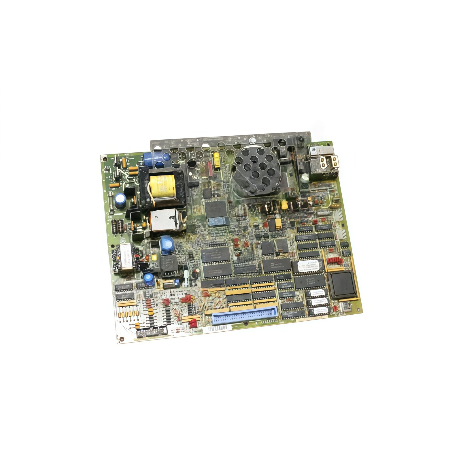
The GE DS200TCEAG1B DS200TCEAG1BSF measures 280 mm in height. Its width reaches 185 mm, and the depth equals 30 mm. The GE DS200TCEAG1B DS200TCEAG1BSF weighs approximately 0.42 kilograms. A single multilayer PCB holds all speed monitoring and logic circuits. The board contains no energy storage capacitors or batteries. Two 50-pin ribbon connectors provide system interface connections. Three speed sensor inputs accept magnetic pickup signals. Four test points allow signal monitoring with an oscilloscope.
| Parameter | Specification |
|---|---|
| Model | GE DS200TCEAG1B DS200TCEAG1BSF |
| Category | Emergency Overspeed Board |
| Dimensions (H x W x D) | 280 mm x 185 mm x 30 mm |
| Weight | 0.42 kg |
| PCB Layers | 6 |
| Energy Storage | None |
| System Connectors | 2 x 50-pin ribbon |
| Sensor Inputs | 3 (magnetic pickup) |
| Test Points | 4 |
| Temperature Range | -20°C to +55°C |
Overspeed Monitoring Specifications
The GE DS200TCEAG1B DS200TCEAG1BSF accepts speed signals from three independent magnetic pickups. It triggers an emergency shutdown at 110 percent of rated turbine speed. Response time from overspeed detection to output activation stays below 15 milliseconds. Consequently, this board provides triple-redundant protection for critical turbine applications. The board includes programmable overspeed setpoints via onboard jumpers. Three relay outputs activate the emergency trip solenoid in a voting configuration. A built-in self-test circuit verifies board functionality during operation.
Installation and Diagnostic Features
You must insert the GE DS200TCEAG1B DS200TCEAG1BSF firmly into a dedicated Mark V rack slot. Transitioning to wiring, use shielded twisted-pair cables for speed sensor connections. Four front LEDs show power, speed status, and trip condition clearly. For testing, use a signal generator at the test points. Always power off the system before removing or inserting the board. The operating temperature range spans from -20°C to +55°C reliably.
Details
| Weight | 0.1 kg |
|---|---|
| Dimensions | 25 × 108 × 127 mm |

Reviews
There are no reviews yet.