
Signal Termination for AC2000 and EX2000 Systems
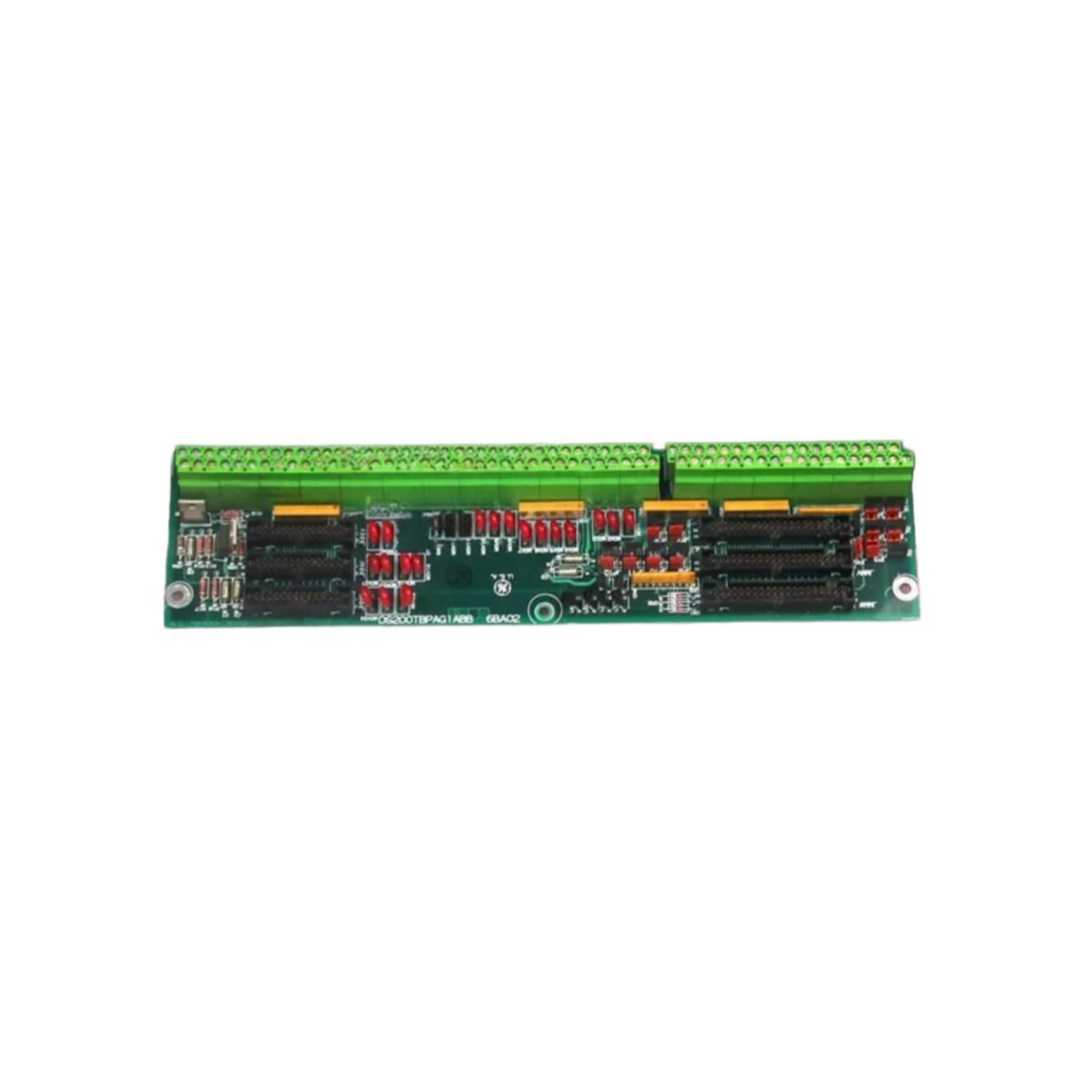
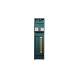
The GE DS200TBPAG1A DS200TBPAG1ABB provides termination for field wiring connections. This board interfaces between field cables and internal drive control boards. It organizes and protects all incoming and outgoing signals.
Technical Specifications
| Parameter | Specification |
|---|---|
| Model | DS200TBPAG1A DS200TBPAG1ABB |
| Category | Termination Board |
| Height | 200 mm |
| Width | 180 mm |
| Depth | 25 mm |
| Weight | 0.520 kg |
| Terminal Type | Screw clamp (pluggable) |
| Number of Terminals | 50 total |
| Terminal Pitch | 5.08 mm |
| Wire Gauge Range | 24 to 12 AWG |
| Voltage Rating | 300 V AC/DC |
| Current Rating | 10 A per terminal |
| Connector Type (Internal) | 2 x 20-pin ribbon cable headers |
| Number of Headers | 3 x 20-pin (field to control) |
| Ground Terminals | 4 x (chassis ground) |
| Shield Clamps | 2 x (cable shield termination) |
| Labeling | Pre-printed (function per terminal) |
| Status Indicators | None (passive device) |
| Internal Components | 1 PCB, 50 screw terminals, 3 headers, 2 shield clamps |
| Energy Storage | None (no battery or capacitor) |
Termination Architecture and Field Wiring
The GE DS200TBPAG1A DS200TBPAG1ABB features 50 screw clamp terminals for field connections. Each terminal accepts wire gauges from 24 to 12 AWG. The board organizes signals into functional groups for easy identification. Pre-printed labels indicate the purpose of each terminal group. Three 20-pin ribbon cable headers connect to internal control boards. The DS200TBPAG1A DS200TBPAG1ABB routes signals between field and drive electronics.
Signal Organization and Grouping
This termination board separates signals into logical functional categories. Analog input terminals occupy the left section of the board. Analog output and digital I/O terminals sit in the center section. Power and ground connections use the right section of the board. The GE DS200TBPAG1A DS200TBPAG1ABB includes four dedicated chassis ground terminals. Each shield clamp secures the drain wire of shielded cables.
Connection Security and Maintenance
Screw clamp terminals provide secure, vibration-resistant connections. Each terminal accepts solid or stranded copper wire only. A screwdriver slot allows easy tightening and loosening of connections. The DS200TBPAG1A DS200TBPAG1ABB uses pluggable terminal blocks for each section. You can remove individual blocks without disturbing other wiring. This design simplifies board replacement and maintenance significantly.
Physical Dimensions and Installation Guidelines
The GE DS200TBPAG1A DS200TBPAG1ABB weighs 0.520 kilograms for secure mounting. Its height measures 200mm, width 180mm, and depth 25mm. Install this board inside the drive cabinet near the cable entry point. The board consumes no electrical power for its operation. It operates reliably from -20°C to +70°C ambient temperature. Use proper strain relief for all field cables entering the board.
Energy Storage and Passive Operation
The DS200TBPAG1A DS200TBPAG1ABB stores no electrical energy internally. It contains zero batteries or capacitors of any kind. Hence, this termination board requires no periodic maintenance whatsoever. You will never replace batteries or perform discharge procedures. The GE DS200TBPAG1A DS200TBPAG1ABB contains no active components to fail. Its passive design guarantees decades of reliable service life.
Details
| Weight | 0.1 kg |
|---|---|
| Dimensions | 25 × 108 × 127 mm |
Reviews
There are no reviews yet.