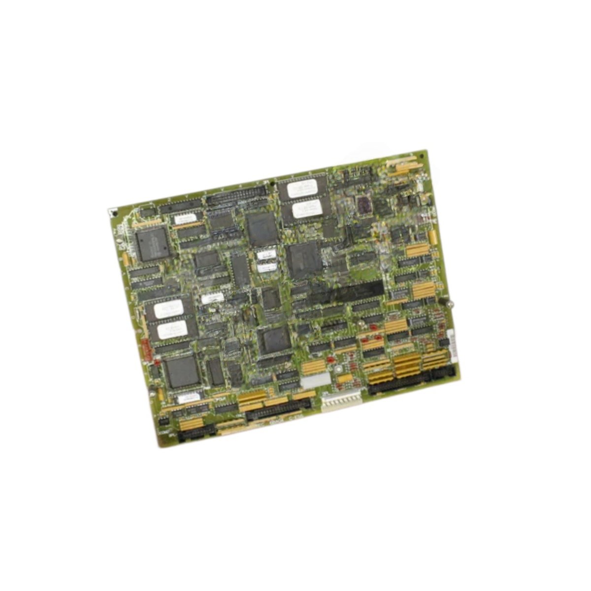
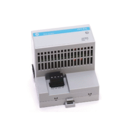
This board manages drive control functions for Mark V turbine systems. The GE DS200SDCCG4A DS200SDCCG4AEC handles speed regulation and torque control algorithms. It measures 250 mm in width and 180 mm in height. This unit weighs approximately 0.64 kg for panel mounting.
Technical Specifications Table
| Parameter | Value |
|---|---|
| Product Model Pair | DS200SDCCG4A DS200SDCCG4AEC |
| Brand | GE Energy / General Electric |
| Category | Drive Control Board |
| Compatible Series | Mark V Turbine Control |
| Processor Type | 32-bit floating-point DSP |
| Clock Speed | 40 MHz |
| Control Algorithms | Speed, torque, position, current regulation |
| Analog Inputs | 6 channels (16-bit resolution) |
| Analog Outputs | 4 channels (14-bit resolution) |
| Digital I/O | 12 inputs / 8 outputs |
| Dimensions (W x H x D) | 250 mm x 180 mm x 30 mm |
| Weight | 0.64 kg |
| Connector Types | 3 x 20-pin headers, 1 x ribbon cable port |
| Internal Components | 1 x DSP, 1 x FPGA, 2 x flash memory chips |
| User Memory | 1 MB flash for firmware |
| Runtime Memory | 512 KB SRAM |
| Energy Storage | 4 x 470 µF capacitors, 1 x super capacitor (72h RTC) |
| PWM Outputs | 6 channels (20 kHz switching) |
| Operating Voltage | 24 V DC external supply |
| Power Consumption | 480 mA maximum |
| LED Indicators | 8 x status (Power, Run, Fault, PWM Active) |
| Operating Temperature | -30°C to 65°C |
Internal Design and Drive Processing
This drive control board uses a 32-bit floating-point DSP for real-time control. An FPGA manages I/O expansion and PWM signal generation. The GE DS200SDCCG4A DS200SDCCG4AEC executes speed, torque, and position regulation algorithms. Six analog inputs provide feedback from current and voltage sensors. Six PWM outputs drive the power inverter stage at 20 kHz. Consequently, this board delivers precise motor control for turbine applications.
Installation and Wiring Guide
First, mount this control board onto standoffs inside your drive cabinet. Next, connect a 24 V DC power supply to the designated terminals. Then, wire your analog feedback sensors to the 6 input channels. Connect the PWM outputs to the power inverter gate driver board. Use shielded cables for all analog signal connections. The board provides LED indicators for power, run status, and fault conditions. Eight status LEDs show real-time operating conditions. This drive control board works with Mark V turbine systems and compatible power inverters. Always verify grounding connections before applying power to the board.
Details
| Weight | 0.45 kg |
|---|---|
| Dimensions | 170 × 145 × 65 mm |
Reviews
There are no reviews yet.