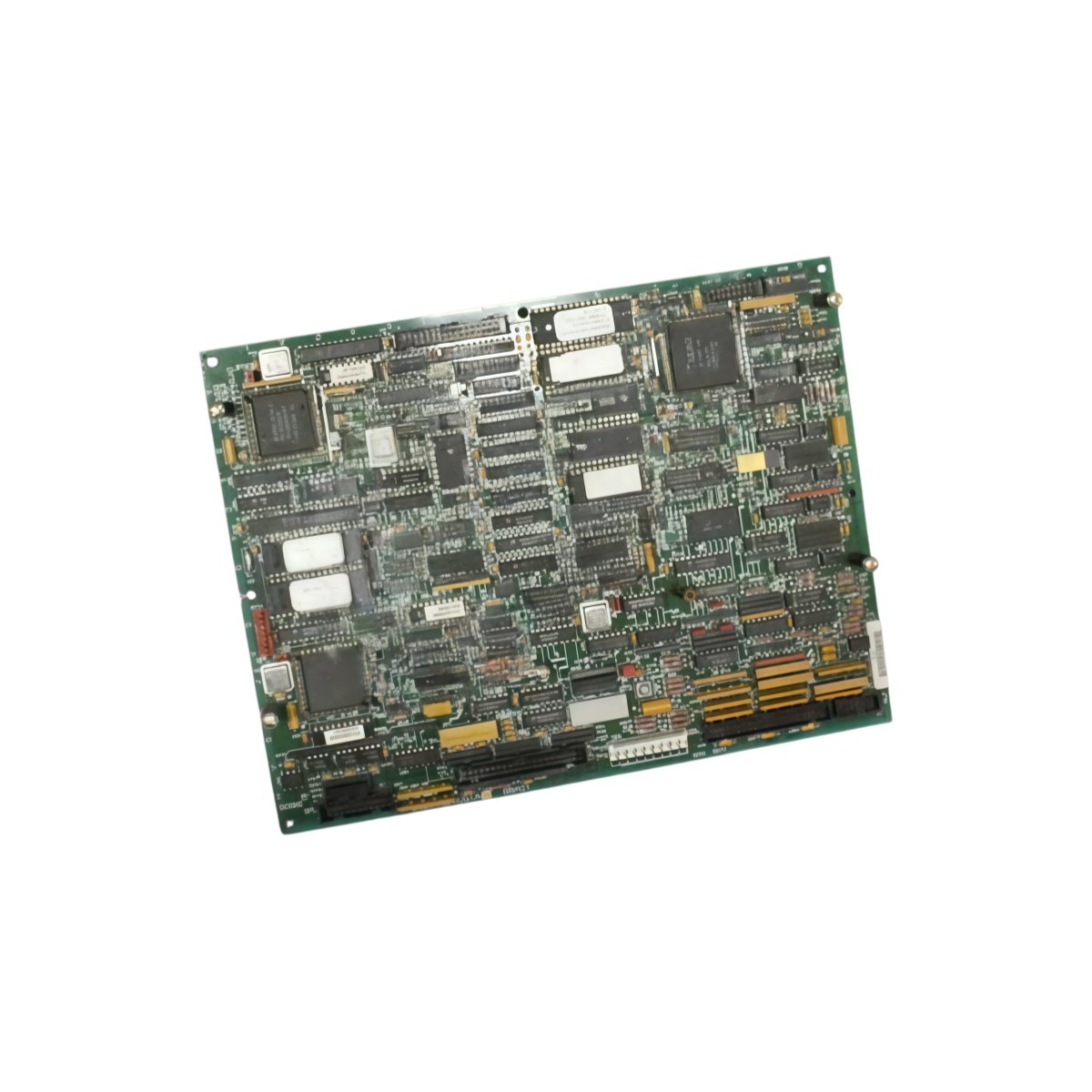
This card manages braking functions for Speedtronic Mark V turbine systems. The GE DS200SBCBG1A DS200SBCBG1ADC controls dynamic braking resistors during deceleration events. It measures 200 mm in width and 150 mm in height. This unit weighs approximately 0.48 kg for panel mounting.
Technical Specifications Table
| Parameter | Value |
|---|---|
| Product Model Pair | DS200SBCBG1A DS200SBCBG1ADC |
| Brand | GE Energy / General Electric |
| Category | Speedtronic Brake Control Card |
| Compatible Series | Mark V Speedtronic Turbine Control |
| Brake Control Channels | 2 independent channels |
| Max Brake Current | 100 A per channel |
| PWM Switching Frequency | 5 kHz |
| Input Signals | 2 x brake enable (24 V DC) |
| Output Signals | 2 x gate drive (15 V DC) |
| Dimensions (W x H x D) | 200 mm x 150 mm x 25 mm |
| Weight | 0.48 kg |
| Connector Types | 2 x 6-pin power headers, 1 x 20-pin ribbon |
| Internal Components | 1 x 16-bit CPU, 2 x gate drivers, 1 x current sensor |
| User Memory | 64 KB flash for configuration |
| Energy Storage | 2 x 470 µF capacitors, 1 x super capacitor (72h) |
| Fault Detection | Overcurrent, overtemperature, short circuit |
| Operating Voltage | 24 V DC external supply |
| Power Consumption | 150 mA maximum |
| LED Indicators | 4 x status (Power, Brake1, Brake2, Fault) |
| Operating Temperature | -30°C to 65°C |
Internal Design and Brake Control Processing
This brake control card uses a 16-bit CPU for braking algorithm execution. Two gate drivers control external IGBTs for dynamic braking. The GE DS200SBCBG1A DS200SBCBG1ADC monitors brake current through onboard sensors. The card activates braking resistors when DC bus voltage exceeds set thresholds. Two 470 µF capacitors filter power supply ripple for clean operation. Consequently, this device safely dissipates regenerative energy from turbine deceleration.
Installation and Wiring Guide
First, mount this brake control card onto standoffs inside your drive cabinet. Next, connect a 24 V DC power supply to the designated terminals. Then, wire the gate drive outputs to the external IGBT modules. Connect the brake enable signals from the main drive controller. Use high-current cables for the brake resistor connections. The card provides LED indicators for power, brake activity, and fault conditions. Four status LEDs show real-time braking operation. This brake control card works with Mark V Speedtronic systems and compatible braking resistors. Always verify the resistor wattage rating matches your application requirements.
Details
| Weight | 0.1 kg |
|---|---|
| Dimensions | 25 × 108 × 127 mm |
Reviews
There are no reviews yet.