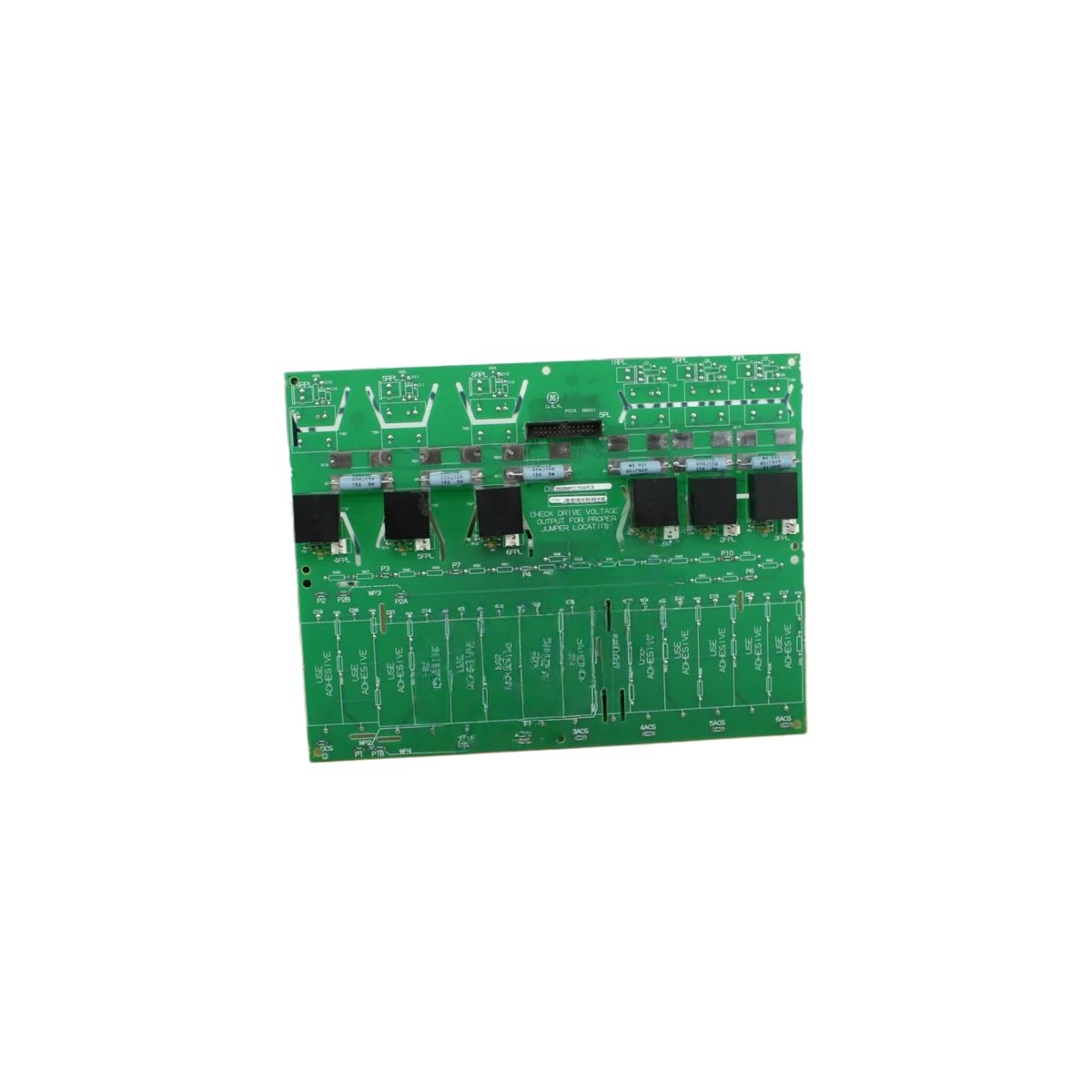
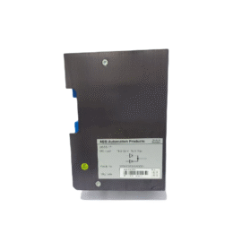
This power connect board distributes DC power throughout GE drive systems. It connects the main power supply to various control and gate driver boards. The unit mounts inside the drive cabinet as a central power hub.
Technical specifications
| Parameter | Specification |
|---|---|
| Brand | GE Energy |
| Model 1 | DS200PCCAG6A |
| Model 2 | DS200PCCAG6ACB |
| Product Family | Mark V / Drive Control |
| Category | Power Connect Board |
| PCB Layer Count | 4 layers |
| Base Material | FR-4 flame retardant |
| Component Count | Approximately 95 components |
| Integrated Circuits | 10 ICs (power management, drivers) |
| Connector Types | 4 x 20-pin headers, 2 x terminal blocks |
| Power Input | 24V DC from main supply |
| Power Outputs | 5V, 12V, 24V regulated rails |
| Current Capacity | 5A total (distributed) |
| Test Points | 8 gold-plated test points |
| Fuse Protection | 2 x 5A fuses (input protection) |
| Status Indicators | 3 x LEDs (PWR, 5V OK, 12V OK) |
| Dimensions (L x W) | Approx. 24 cm x 16 cm |
| Thickness | Approx. 1.6 mm |
| Weight | Approx. 0.3 kg |
| Energy Storage | 8 x electrolytic capacitors (100 µF each) |
| Operating Temperature | 0°C to 55°C |
| Mounting | 4 x screw holes (M4) |
Detailed Technical Analysis
This power connect board distributes DC power to multiple drive sub-systems. It accepts a 24V DC input from the main power supply. The board then generates regulated 5V and 12V outputs for other cards. Approximately 95 components populate both sides of this circuit board.
Now let us examine its power management features. This board draws input power through two 5A fuses for protection. Eight electrolytic capacitors filter all three output voltage rails. Each capacitor stores 100 microfarads of electrical charge. Ten integrated circuits handle power regulation and distribution tasks.
This power connect board features three LED status indicators. A green PWR LED shows the 24V input is present. Separate green LEDs confirm 5V and 12V outputs are stable. Eight gold-plated test points allow voltage monitoring with a multimeter. The board connects to other cards via four header connectors.
Installation and Connection Guidelines
You mount this board using four M4 screws with insulating standoffs. Connect the 24V DC input to the main terminal block. This board automatically generates the secondary voltage rails upon power-up. Verify all output voltages before connecting sensitive downstream boards.
Use proper ESD precautions when handling this power board. The ICs and capacitors are sensitive to static discharge. Always power down the drive before inserting or removing this board. Replace blown fuses only with identical 5A fast-blow types.
Practical Applications
Engineers use this power board for GE drive repair and restoration. It serves as a direct replacement for failed original power boards. This component also works in legacy drive upgrade projects. Its multiple regulated outputs suit complex drive systems.
Summary of Features
To conclude, this power connect board distributes 24V, 12V, and 5V rails. It weighs 0.3 kilograms and includes eight filter capacitors. Choose DS200PCCAG6A DS200PCCAG6ACB for reliable power distribution in drive systems.
Details
| Weight | 0.45 kg |
|---|---|
| Dimensions | 170 × 145 × 65 mm |
Reviews
There are no reviews yet.