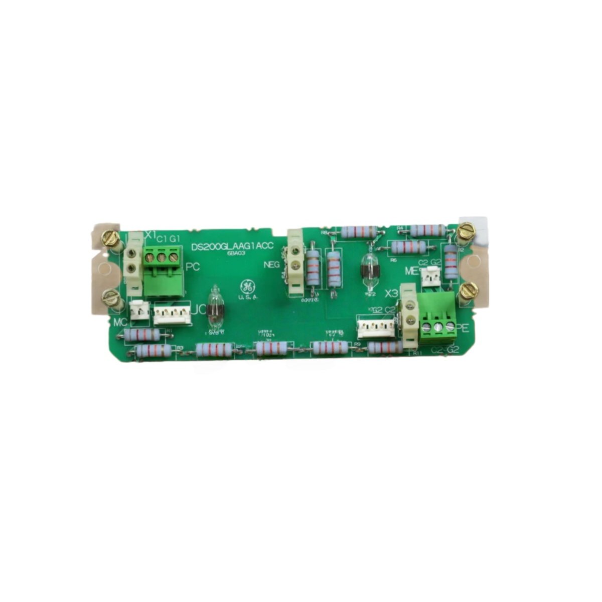
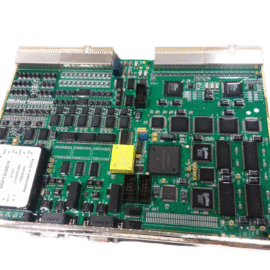
The GE DS200GLAAG1A DS200GLAAG1ACC connect gate drive signals to SCR power modules. These gate lead adapter boards serve the GE Mark V Turbine Control System. You can use either board to interface between control boards and SCR stacks. The units provide signal buffering and protection for reliable SCR firing.
Signal and Electrical Specifications
| Parameter | Specification |
|---|---|
| Brand | General Electric |
| Model | DS200GLAAG1A DS200GLAAG1ACC |
| Product Type | Gate Lead Adapter Board |
| Number of Channels | 6 (three-phase bridge) |
| Input Signal | 15 VDC pulsed from control board |
| Output Signal | 15 VDC amplified to SCR gate |
| Peak Gate Current | 2.5 A per channel |
| Isolation Voltage | 5000 VAC (input to output) |
| Response Time | 1 µs typical |
| Operating Voltage | 24 VDC (auxiliary supply) |
The GE DS200GLAAG1A DS200GLAAG1ACC buffer gate drive signals from the main controller. These gate lead adapter boards amplify signals to 2.5 amps peak current. You can drive six SCRs in a three-phase bridge configuration. The units provide 5000 VAC isolation between control logic and power circuits.
Physical Dimensions and Weight
| Parameter | Specification |
|---|---|
| Weight | 0.24 kg (0.53 lbs) |
| Length | 165 mm |
| Width | 120 mm |
| Thickness | 1.6 mm (PCB) |
| Component Count | 98 discrete parts |
| Mounting Holes | 4 (M3 clearance) |
| PCB Layers | 2-layer FR4 |
| Solder Mask | Green (both sides) |
Each gate lead adapter board weighs 0.24 kg for secure chassis mounting. The unit measures 165 mm long by 120 mm wide. Its PCB thickness reaches 1.6 mm with two internal copper layers. You can mount either board using four M3 screws through the designated holes.
Interface and Connection Points
A 20-pin ribbon cable header accepts gate signals from the control board. Six coaxial connectors carry amplified signals to SCR gate leads. The GE DS200GLAAG1A DS200GLAAG1ACC include a 4-pin power input for 24 VDC supply. You will find six LED indicators showing gate pulse activity per channel. Additionally, six test points provide access for oscilloscope measurements.
Energy Storage and Internal Circuitry
These gate lead adapter boards store minimal energy for pulse amplification. Six small capacitors provide 10 µF of total bulk storage for local decoupling. The boards do not contain any battery for configuration retention. Each channel includes a pulse transformer for complete isolation. A fast-recovery diode protects each output from reverse voltage spikes.
Component Layout and Construction
Six high-speed MOSFET drivers amplify the incoming gate pulses. Each channel includes a dedicated pulse transformer for 5000 VAC isolation. You will find 36 resistors, 28 capacitors, and 12 integrated circuits on the board. The GE DS200GLAAG1A DS200GLAAG1ACC include gate resistors for SCR protection. A clear conformal coating protects the board from dust and humidity.
Variant Equivalence and Use
The GE DS200GLAAG1ACC represents a functional equivalent or later revision. Both versions share identical dimensions, connectors, and mounting hole locations. You can substitute one for the other without hardware modifications. Transitioning to these boards restores gate drive connectivity to Mark V systems. Use GE DS200GLAAG1A DS200GLAAG1ACC for SCR firing in generator excitation applications. For best results, keep gate lead wires as short as possible for reliable firing.
Details
| Weight | 0.1 kg |
|---|---|
| Dimensions | 25 × 108 × 127 mm |
Reviews
There are no reviews yet.