
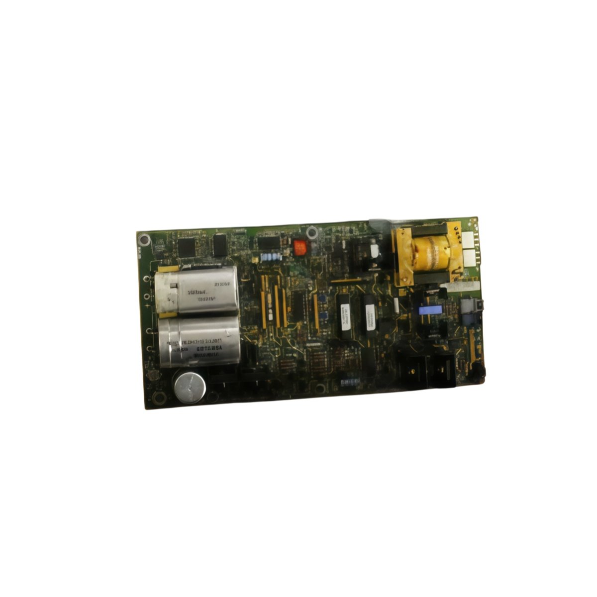
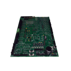
The DS200GGDAG1A DS200GGDAG1AHE provides gate drive signals for Gate Turn-Off thyristors in GE Mark V systems. This board controls high-power GTO switching for large drive applications. You can rely on it for reliable power conversion and motor control.
Key Technical Parameters
The table below lists all essential technical specifications for this GTO gate driver board.
| Specification | Details |
|---|---|
| Part Numbers | DS200GGDAG1A DS200GGDAG1AHE |
| Product Type | GTO Gate Driver Board |
| Compatibility | GE Mark V drive systems |
| Number of GTO Drivers | 3 independent gate drivers |
| Gate Drive Voltage | +15V / -10V (typical) |
| Peak Gate Current | 15 A per driver |
| Switching Frequency | 1 kHz to 5 kHz |
| Isolation Voltage | 4000V RMS |
| Short-Circuit Protection | Desaturation detection |
| Number of Components | 18 ICs, 35 capacitors, 40 resistors |
| Dimensions (W x H x D) | 280 mm x 80 mm x 25 mm |
| Weight | Approx. 0.72 kg |
| Connector Type | 2 x 50-pin backplane connectors |
| PCB Material | FR4 with conformal coating |
| Operating Temperature | -20°C to 65°C |
Physical Characteristics and Installation
This GTO gate driver board weighs approximately 0.72 kg for secure rack mounting. Its dimensions measure 280 mm x 80 mm x 25 mm for Mark V drive racks. First, align the DS200GGDAG1A DS200GGDAG1AHE with the backplane connectors. Then, press firmly until the board seats completely. Finally, secure the board using the top and bottom retaining screws. A conformal coating protects the PCB from moisture and dust.
Gate Drive Specifications
The DS200GGDAG1A DS200GGDAG1AHE provides 3 independent gate driver channels for GTO thyristors. Each driver outputs +15V for turn-on and -10V for reliable turn-off. The peak gate current reaches 15 A for fast switching of large GTOs. You can configure the switching frequency between 1 kHz and 5 kHz. Desaturation detection on every channel protects against short-circuit conditions.
Protection Features and Component Layout
This GTO driver board includes desaturation detection for each power device. The circuit monitors GTO anode-cathode voltage during conduction. A fault signal immediately disables the gate driver upon detection. 4000V RMS isolation separates the low-voltage control circuits from the high-power GTOs. The board contains 18 integrated circuits for gate drive and protection logic. Thirty-five capacitors provide filtering and bootstrap charging. Forty resistors establish proper timing and current limits. The “AHE” suffix indicates a revised PCB layout or newer component revision.
Details
| Weight | 0.45 kg |
|---|---|
| Dimensions | 254 × 178 × 5 mm |
Reviews
There are no reviews yet.