
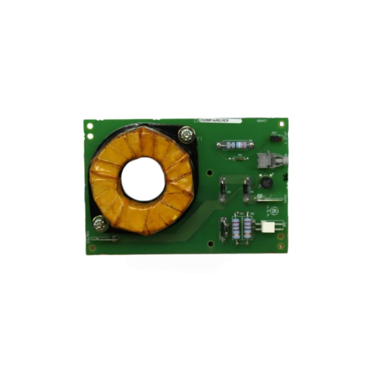
This SCR high voltage gate interface board triggers thyristors in GE drive systems. It generates gate pulses for high-power SCR modules in the rectifier bridge. The unit mounts inside the drive cabinet near the power stack.
Technical specifications
| Parameter | Specification |
|---|---|
| Brand | GE Energy |
| Model 1 | DS200FHVAG1A |
| Model 2 | DS200FHVAG1ACA |
| Product Family | Mark V / Drive Control |
| Category | SCR High Voltage Gate Interface Board |
| PCB Layer Count | 6 layers |
| Base Material | High-Tg FR-4 |
| Number of Gate Channels | 6 (six) independent channels |
| Output Voltage | 15V gate pulse |
| Output Current | 1.5 A peak per channel |
| Pulse Width | 30 microseconds typical |
| Isolation Voltage | 3500V RMS (optical) |
| Input Control Signal | Fiber optic (TTL compatible) |
| SCR Types | Phase control thyristors |
| Component Count | Approximately 120 components |
| Integrated Circuits | 12 ICs (driver, optocouplers, logic) |
| Connector Types | 6 x screw terminals, 2 x fiber ports |
| Power Supply | 24V DC external |
| Current Consumption | 200 mA typical |
| Status Indicators | 6 x LEDs (gate active per channel), 1 x PWR |
| Test Points | 8 gold-plated test points |
| Energy Storage | 10 x electrolytic capacitors (100 µF each) |
| Dimensions (L x W) | Approx. 28 cm x 18 cm |
| Thickness | Approx. 2.5 cm |
| Weight | Approx. 0.35 kg |
| Operating Temperature | 0°C to 55°C |
| Mounting | 4 x screw holes (M5) |
Detailed Technical Analysis
This gate interface board drives six independent SCR channels for three-phase control. It receives firing commands via fiber optic links from the main controller. Each channel delivers a 15V gate pulse at 1.5 amps peak current. The pulse width is 30 microseconds for reliable SCR turn-on.
Now let us examine its isolation features. This board provides 3500V RMS optical isolation between control and power circuits. Approximately 120 components populate both sides of this 6-layer PCB. Twelve integrated circuits include gate drivers and optocouplers. Ten electrolytic capacitors store energy for the gate pulse circuits.
This gate board draws 200 milliamps from a 24V DC external supply. Six LEDs show gate activity for each individual channel. Eight gold-plated test points allow pulse verification with an oscilloscope. The board connects to SCR gates via screw terminal blocks.
Installation and Connection Guidelines
You mount this board using four M5 screws with insulating standoffs. Connect the 24V DC power supply to the designated terminals. Wire each SCR gate to the corresponding output terminal. Connect the fiber optic cables from the control board to the input ports.
Use proper high voltage safety precautions when working near the power stack. The SCR circuits can carry dangerous voltages even at low currents. Verify gate pulse timing before connecting to actual SCR modules. Always discharge the DC bus capacitors before handling this board.
Practical Applications
Engineers use this gate board for drive repair and power stack restoration. It provides reliable SCR triggering for three-phase rectifier bridges. This component also works in legacy drive upgrade projects. Its six channels suit standard three-phase drive configurations.
Summary of Features
To conclude, this gate board drives six SCR channels at 1.5 amps peak. It weighs 0.35 kilograms and provides 3500V RMS isolation. Choose DS200FHVAG1A DS200FHVAG1ACA for reliable thyristor firing in drive systems.
Details
| Weight | 0.1 kg |
|---|---|
| Dimensions | 25 × 108 × 127 mm |
Reviews
There are no reviews yet.