
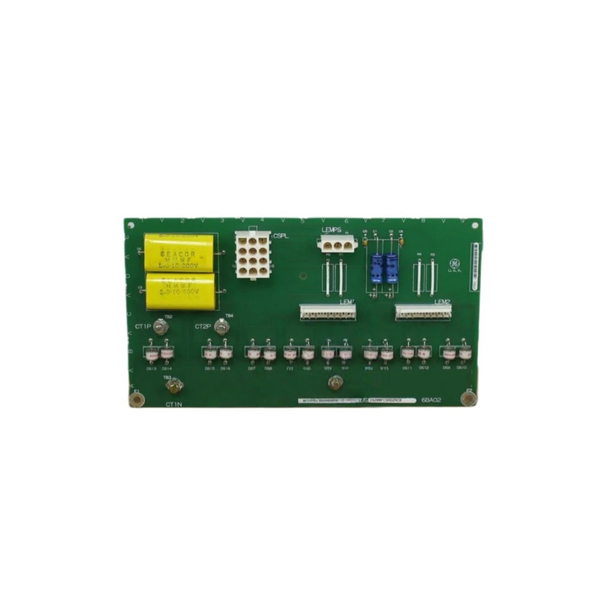
This current sensing interface board measures phase and ground currents in GE drives. It converts analog current signals into digital data for the main controller. The unit mounts inside the drive cabinet near the power electronics.
Technical specifications
| Parameter | Specification |
|---|---|
| Brand | GE Energy |
| Model 1 | DS200FCSAG2A |
| Model 2 | DS200FCSAG2ACB |
| Product Family | Mark V / Drive Control |
| Category | Current Sensing Interface Board |
| PCB Layer Count | 4 layers |
| Base Material | FR-4 flame retardant |
| Input Channels | 6 (six) current inputs |
| Input Types | 3 x phase current, 3 x ground current |
| Input Range | ±10V or 4-20mA (selectable) |
| ADC Resolution | 14 bits |
| Sampling Rate | 20 kHz per channel |
| Accuracy | ±0.3% of full scale |
| Input Impedance | 100 kΩ (voltage), 250 Ω (current) |
| Bandwidth | 2 kHz per channel |
| Component Count | Approximately 115 components |
| Integrated Circuits | 12 ICs (ADC, op-amps, isolation) |
| Connector Types | 3 x 20-pin headers, 1 x terminal block |
| Power Supply | 24V DC external |
| Current Consumption | 160 mA typical |
| Test Points | 8 gold-plated test points |
| Status Indicators | 2 x LEDs (PWR, DATA) |
| Energy Storage | 8 x electrolytic capacitors (47 µF each) |
| Dimensions (L x W) | Approx. 24 cm x 16 cm |
| Thickness | Approx. 1.6 mm |
| Weight | Approx. 0.29 kg |
| Operating Temperature | 0°C to 55°C |
| Mounting | 4 x screw holes (M4) |
Detailed Technical Analysis
This current sensing board monitors six channels for complete drive protection. It measures three phase currents plus three ground currents continuously. A 14-bit ADC converts each analog signal into digital data with high precision. The board samples each channel at 20 kHz for accurate fault detection.
Now let us examine its signal processing features. Approximately 115 components populate both sides of this 4-layer PCB. Twelve integrated circuits include the ADC and operational amplifiers. The board achieves ±0.3% accuracy across the full input range. Eight electrolytic capacitors filter the power supply for clean operation.
This sensing board draws 160 milliamps from a 24V DC external supply. Two LED indicators show power status and data activity. Eight gold-plated test points allow signal verification during commissioning. The board accepts either voltage or current inputs via jumper selection.
Installation and Connection Guidelines
You mount this board using four M4 screws with insulating standoffs. Connect the 24V DC power supply to the designated terminal block. Wire current transducer outputs to the appropriate input channels. Select voltage or current mode using the jumper blocks on the board.
Use shielded twisted-pair cables for all analog input connections. Proper shielding prevents electrical noise from corrupting current readings. Verify each channel’s input range before applying power to the board. Always power down the drive before inserting or removing this interface board.
Practical Applications
Engineers use this sensing board for drive repair and protection system restoration. It provides critical current feedback for overcurrent detection loops. This component also works in legacy drive upgrade projects. Its six channels suit comprehensive drive protection schemes.
Summary of Features
To conclude, this current sensing board monitors six channels at 20 kHz sampling. It weighs 0.29 kilograms and includes a 14-bit ADC. Choose DS200FCSAG2A DS200FCSAG2ACB for reliable current feedback in drive systems.
Details
| Weight | 0.1 kg |
|---|---|
| Dimensions | 25 × 108 × 127 mm |
Reviews
There are no reviews yet.