
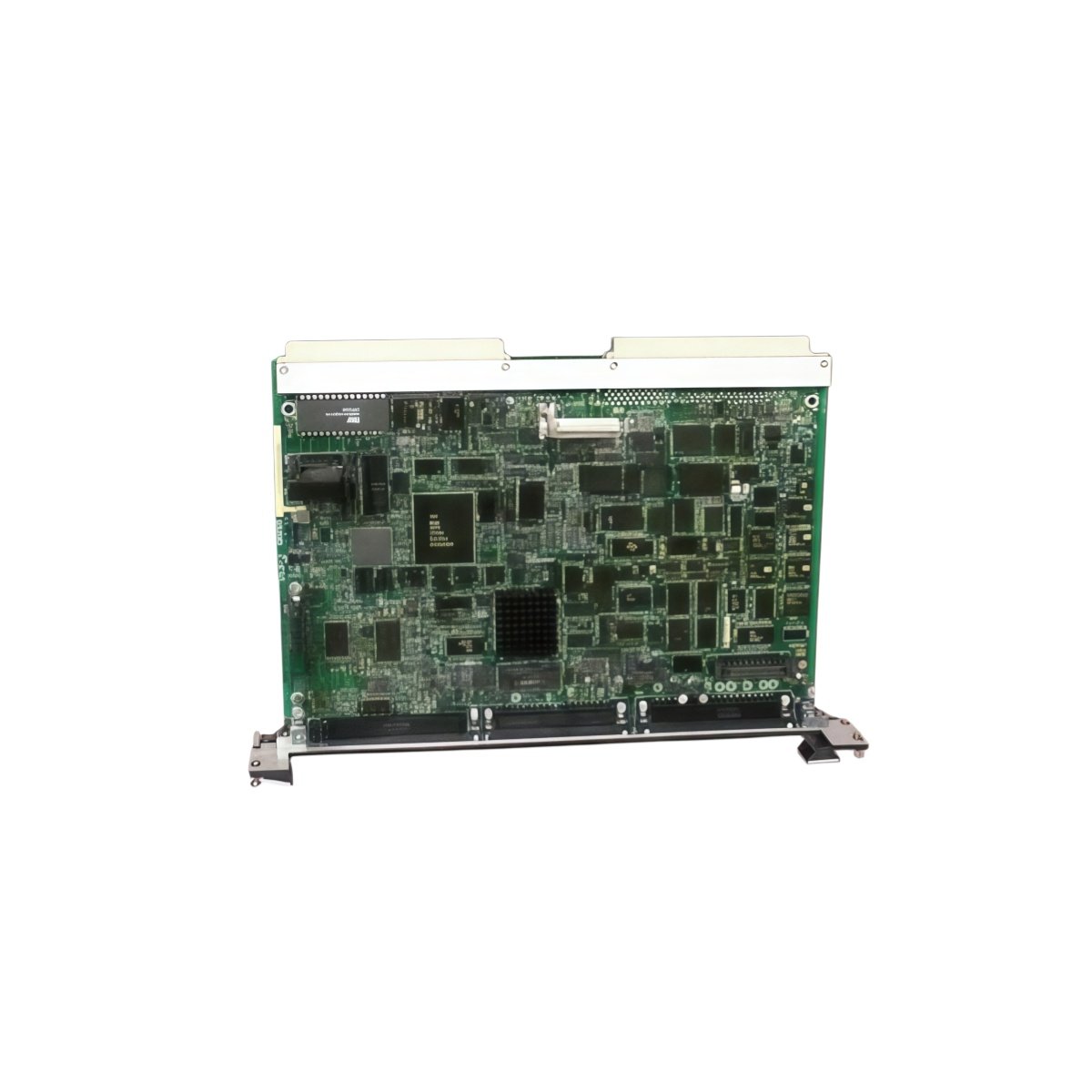
This terminal board expands I/O connectivity for GE Mark V turbine control systems. It organizes field wiring for analog and digital signals in a single location. You will use this board to reduce cabinet clutter and simplify maintenance.
Key Technical Specifications
| Parameter | Details |
|---|---|
| Model Numbers | DS200DSPVH1A DS200DSPVH1ADA |
| Brand | GE (General Electric) |
| Category | Terminal Board / I/O Expansion |
| Dimensions (W x H x D) | 340 mm x 210 mm x 45 mm |
| Weight | 1.5 kg |
| Signal Channels | 48 mixed (configurable as input or output) |
| Onboard Energy Storage | 6 x 330 µF capacitors (1980 µF total) |
| Component Count | 222 discrete components |
| Field Interface | 8 x 20-pin removable terminal blocks |
| Control Interface | 4 x 50-pin ribbon connectors |
| Voltage Rating | 24V DC nominal (5–30V range) |
| Current per Channel | 100 mA for output configuration |
| Status Indicators | 48 green LEDs (one per channel) |
| Wire Gauge | 0.2 mm² to 1.5 mm² (24–16 AWG) |
Physical Layout and Cabinet Mounting
This terminal board measures 340 mm in width and 210 mm in height. Its depth reaches 45 mm for standard panel mounting. The unit weighs 1.5 kilograms due to the robust metal frame. Four M5 mounting holes secure the board to a backplate vertically.
Internal Circuitry and Energy Storage
Two hundred twenty-two components populate this mixed-signal interface board. Six 330 µF capacitors form a 1980 µF total energy storage bank. This bank filters power for both analog and digital circuits. Consequently, the board maintains signal integrity in electrically noisy environments. Each channel includes transient protection for field wiring safety.
Channel Configuration and Signal Routing
Forty-eight channels support field wiring for sensors and actuators. You can configure each channel as an input or output via jumpers. The board routes signals to four 50-pin ribbon connectors for controller interface. Green LEDs illuminate when a channel carries an active signal. This design reduces the number of cables between the controller and field devices.
Field Wiring and Status Indication
Eight removable 20-pin terminal blocks accept wires from 0.2 mm² to 1.5 mm². You can land solid or stranded wires without special crimp tools. Each terminal includes a test point for multimeter troubleshooting. Forty-eight green LEDs show the real-time status of every channel. Therefore, you can diagnose field wiring issues without removing the board.
Compatibility Note
Both DS200DSPVH1A DS200DSPVH1ADA share identical electrical and mechanical specifications. The ADA suffix indicates a later hardware revision with improved terminal labeling. You can use either version interchangeably in any Mark V cabinet. This board works with all Mark V CPU and I/O modules without additional adapters.
Details
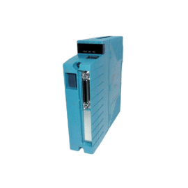
| Weight | 0.1 kg |
|---|---|
| Dimensions | 25 × 108 × 127 mm |
Reviews
There are no reviews yet.