
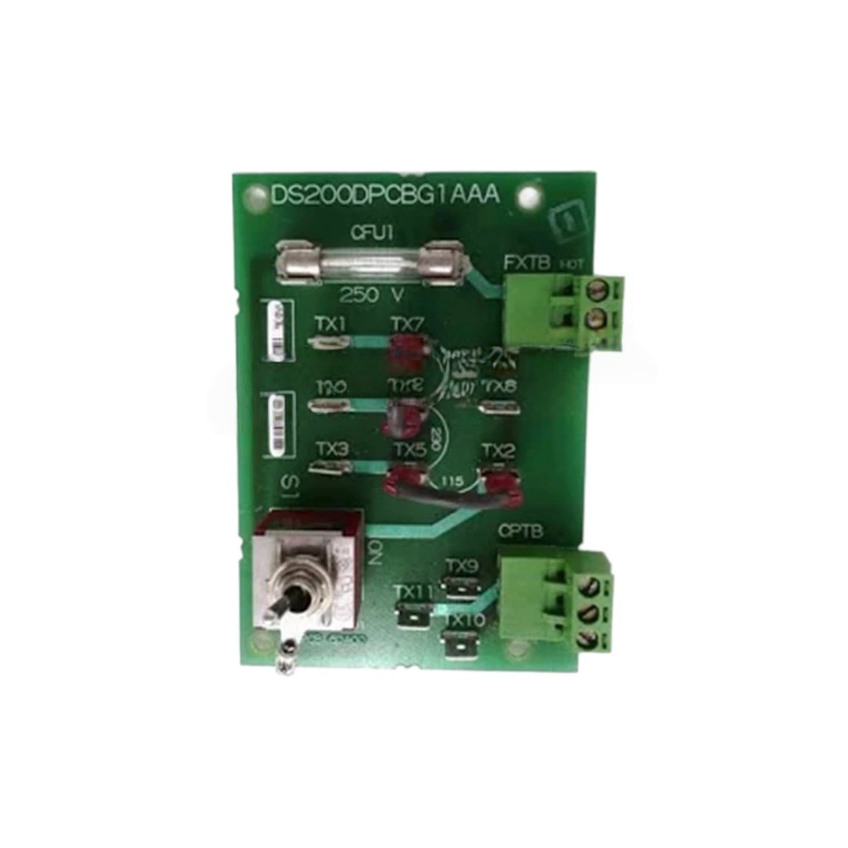
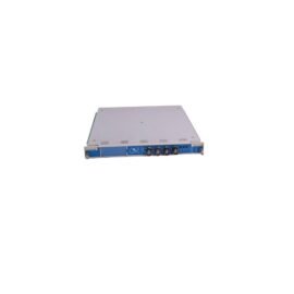
This OS plus power connect board distributes operating system signals and DC power in Mark V systems. It links the main processor board with I/O and power supply modules. You will find this board as a backbone component in GE turbine control cabinets.
Key Technical Specifications
| Parameter | Details |
|---|---|
| Model Numbers | DS200DPCBG1A DS200DPCBG1AAA |
| Brand | GE (General Electric) |
| Category | OS + Power Connect Board |
| Dimensions (W x H x D) | 260 mm x 180 mm x 35 mm |
| Weight | 1.0 kg |
| Power Rails | 5V DC (15A), 24V DC (8A) |
| Onboard Energy Storage | 6 x 1000 µF capacitors (6000 µF total) |
| Component Count | 168 discrete components |
| Processor Interface | 32-pin edge connector |
| I/O Interface | 4 x 50-pin ribbon connectors |
| Power Input | 24V DC from external supply |
| Protection | Overcurrent and thermal shutdown |
| Status Indicators | 4 LEDs (5V OK, 24V OK, OS ACT, FLT) |
| Operating Temperature | 0°C to 60°C |
Physical Layout and Rack Mounting
This power connect board measures 260 mm in width and 180 mm in height. Its depth reaches 35 mm for standard Mark V racks. The unit weighs 1.0 kilogram for straightforward installation into any slot. Two edge connectors plug directly into the backplane for signal distribution.
Internal Circuitry and Energy Storage
One hundred sixty-eight components populate this power distribution board. Six 1000 µF capacitors form a 6000 µF total energy storage bank. This bank decouples both 5V and 24V rails for clean power delivery. Consequently, connected modules receive stable voltage during peak current demands. Multiple power planes distribute current evenly across the board.
Power Distribution and Rail Capacity
The board supplies 5V DC at 15 amps for processor and logic circuits. It also provides 24V DC at 8 amps for I/O modules and field devices. Each rail includes independent overcurrent protection with automatic recovery. A thermal sensor shuts down both rails if the board exceeds 85°C. Green LEDs confirm the presence of each voltage rail.
OS Signal Routing and Interface
A 32-pin edge connector carries operating system signals from the main processor. Four 50-pin ribbon connectors distribute these signals to I/O boards. The board also routes interrupt and status lines between modules. Red LEDs trigger when the board detects a signal fault or missing voltage. This design simplifies cabling inside the turbine control cabinet.
Compatibility Note
Both DS200DPCBG1A DS200DPCBG1AAA share identical electrical and mechanical specifications. The AAA suffix indicates a later hardware revision with enhanced connector retention. You can use either version interchangeably in any Mark V system.
Details
| Weight | 0.1 kg |
|---|---|
| Dimensions | 25 × 108 × 127 mm |
Reviews
There are no reviews yet.