
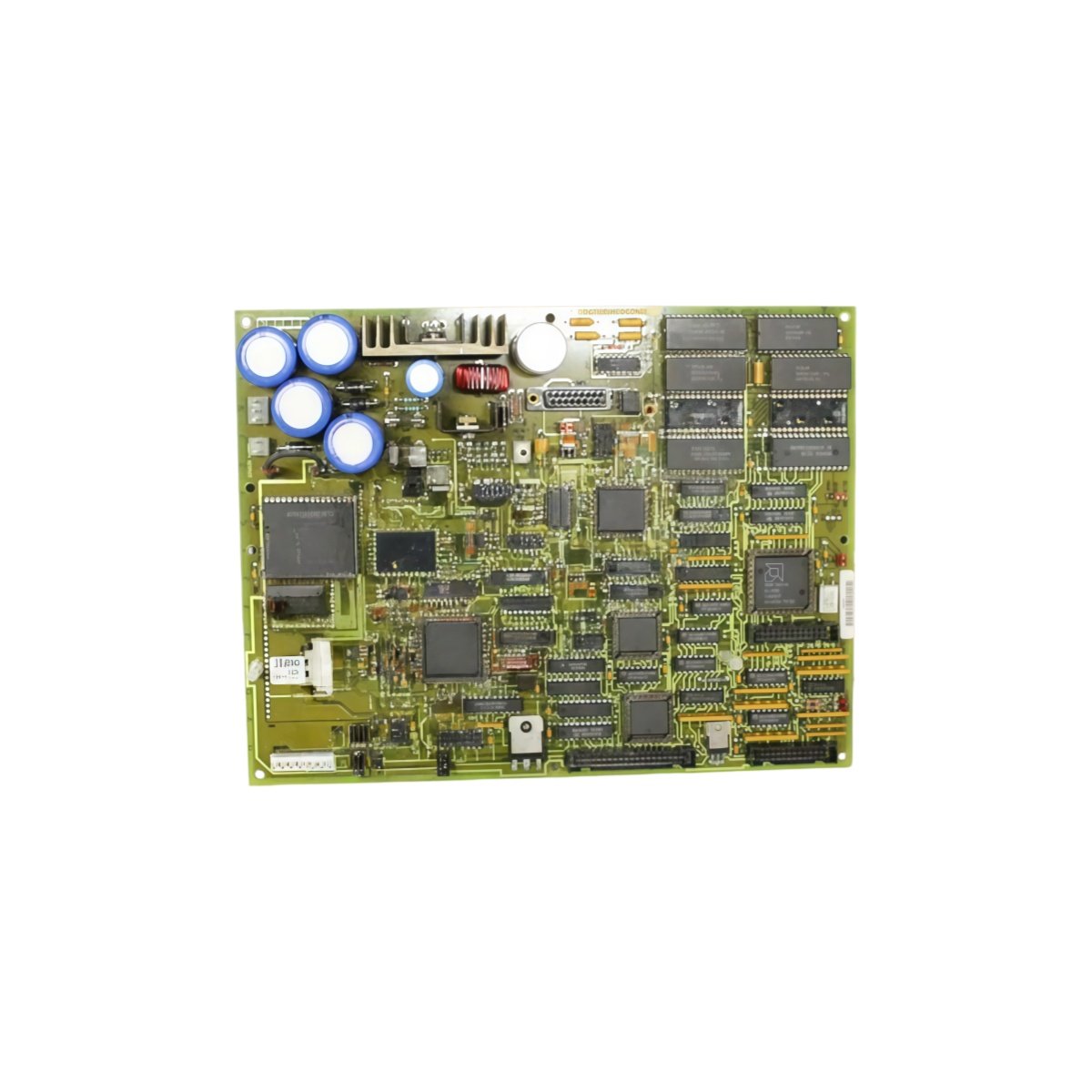
This interface board handles communication between Mark V processors and I/O modules. It routes data signals and provides diagnostic monitoring for the entire system. You will find this board in GE turbine control cabinets for gas and steam applications.
Key Technical Specifications
| Parameter | Details |
|---|---|
| Model Numbers | DS200DMCAG2A DS200DMCAG2AGC |
| Brand | GE (General Electric) |
| Category | Interface Board / I/O Communication |
| Dimensions (W x H x D) | 270 mm x 170 mm x 30 mm |
| Weight | 0.95 kg |
| Communication Channels | 8 independent serial links |
| Onboard Energy Storage | 4 x 680 µF capacitors (2720 µF total) |
| Component Count | 188 discrete components |
| Processor Interface | 32-pin edge connector |
| I/O Interface | 4 x 50-pin ribbon connectors |
| Data Rate | 187.5 kbps per channel |
| Isolation | Optocoupler (1500V) on all I/O lines |
| Diagnostic Features | Loopback and error counters |
| Status Indicators | 8 LEDs (one per channel) |
Physical Layout and Rack Mounting
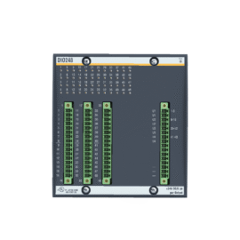
This interface board measures 270 mm in width and 170 mm in height. Its depth reaches 30 mm for standard Mark V racks. The unit weighs 0.95 kilograms for straightforward slot installation. Two card guides secure the board firmly to the backplane.
Internal Circuitry and Energy Storage
One hundred eighty-eight components populate this communication interface board. Four 680 µF capacitors form a 2720 µF total energy storage bank. This bank filters power supply noise for all eight serial channels. Consequently, the board maintains error-free communication in noisy environments. Each channel includes a dedicated buffer and line driver circuit.
Communication Architecture and Data Rate
The board supports eight independent serial links to remote I/O modules. Each channel operates at 187.5 kbps for real-time data exchange. The processor interface uses a 32-pin edge connector for high-speed access. Green LEDs illuminate when each channel actively transmits or receives data. Error counters help diagnose cable or termination issues in the field.
Isolation and Diagnostic Features
Optocoupler isolation provides 1500V protection on all I/O communication lines. This barrier prevents ground loops and surge damage from field cabling. Loopback test capability verifies each channel’s hardware integrity. The board also monitors CRC errors and link status continuously. Red LEDs indicate channels with communication faults or timeouts.
Compatibility Note
Both DS200DMCAG2A DS200DMCAG2AGC share identical electrical specifications. The AGC suffix indicates a later hardware revision with improved noise filtering. You can use either version interchangeably in any Mark V system. This board works with all Mark V I/O modules and remote racks without configuration changes.
Details
| Weight | 0.1 kg |
|---|---|
| Dimensions | 25 × 108 × 127 mm |
Reviews
There are no reviews yet.