
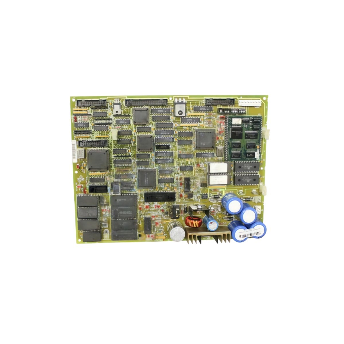
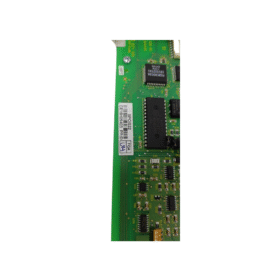
This interface board conditions and routes analog signals within GE Mark V systems. It connects field transmitters to the main turbine controller for accurate process monitoring. You will find this board in power generation plants and industrial turbine applications.
Key Technical Specifications
| Parameter | Details |
|---|---|
| Model Numbers | DS200DMCAG1A DS200DMCAG1AHC |
| Brand | GE (General Electric) |
| Category | Interface Board / Signal Conditioning |
| Dimensions (W x H x D) | 270 mm x 170 mm x 30 mm |
| Weight | 0.98 kg |
| Analog Input Channels | 12 differential (4–20 mA or 0–10V) |
| Analog Output Channels | 6 single-ended (4–20 mA) |
| Onboard Energy Storage | 5 x 470 µF capacitors (2350 µF total) |
| Component Count | 204 discrete components |
| Processor Interface | 32-pin edge connector |
| Field Interface | 6 x 10-pin removable terminal blocks |
| Accuracy | ±0.1% of full scale |
| Input Impedance | 250 Ω (current) or 100 kΩ (voltage) |
| Isolation | 1500V between field and logic |
Physical Layout and Rack Mounting
This interface board measures 270 mm in width and 170 mm in height. Its depth reaches 30 mm for standard Mark V racks. The unit weighs 0.98 kilograms for straightforward slot installation. Two card guides secure the board firmly to the backplane.
Internal Circuitry and Energy Storage
Two hundred four components populate this precision analog interface board. Five 470 µF capacitors form a 2350 µF total energy storage bank. This bank filters power supply noise for all analog circuits. Consequently, the board maintains accurate signal conversion in noisy environments. Each channel includes programmable gain and filtering options.
Analog Input Configuration and Signal Range
Twelve differential channels accept 4–20 mA or 0–10V from field transmitters. You can select current or voltage mode via onboard jumpers. Current inputs present 250 Ω resistance to the transmitter loop. Voltage inputs offer 100 kΩ impedance for minimal signal loading. Green LEDs indicate active channels during normal operation.
Analog Output Configuration and Drive Capacity
Six single-ended channels provide 4–20 mA signals to actuators and positioners. Each output drives up to 500 Ω load at 24V DC supply. The board includes open-loop detection for output wiring faults. Red LEDs illuminate when any output channel encounters a fault condition. Removable terminal blocks accept wires from 0.2 mm² to 1.5 mm².
Isolation and Compatibility
A 1500V isolation barrier separates field wiring from the processor backplane. This protection prevents ground loops and surge damage to sensitive circuits. Both DS200DMCAG1A DS200DMCAG1AHC share identical electrical specifications. The AHC suffix indicates a later hardware revision with enhanced analog filtering. You can use either version interchangeably in any Mark V system.
Details
| Weight | 0.1 kg |
|---|---|
| Dimensions | 25 × 108 × 127 mm |
Reviews
There are no reviews yet.