
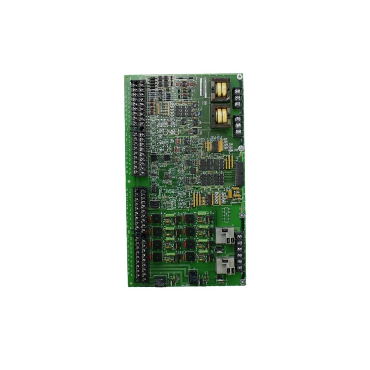
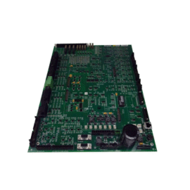
This LCI auxiliary I/O terminal board provides field wiring termination for auxiliary signals. It connects sensors and actuators to the main LCI drive control system. The unit mounts on a DIN rail inside the drive cabinet.
Technical specifications
| Parameter | Specification |
|---|---|
| Brand | GE Energy |
| Model 1 | DS200DDTBG2A |
| Model 2 | DS200DDTBG2ABB |
| Product Family | Mark V / LCI Drive Control |
| Category | LCI Auxiliary I/O Terminal Board |
| PCB Layer Count | 4 layers |
| Base Material | FR-4 flame retardant |
| Digital Inputs | 16 (sixteen) 24V DC |
| Digital Outputs | 16 (sixteen) transistor, 0.5A |
| Terminal Type | Screw clamp (fixed) |
| Wire Gauge | 24 to 14 AWG |
| Voltage Rating | 250V AC / 30V DC maximum |
| Current Rating | 2A per terminal |
| Connector Type (I/O side) | 4 x 20-pin ribbon cable headers |
| Connector Type (Field side) | 32 x screw terminals (2 per channel) |
| Component Count | 1 PCB, 32 terminal blocks, 4 ribbon connectors |
| Status Indicators | None (passive I/O) |
| Power Supply | 24V DC external (field power) |
| Current Consumption | 100 mA (logic) + load current |
| Dimensions (L x W x H) | Approx. 24 cm x 14 cm x 5 cm |
| Weight | Approx. 0.48 kg |
| Energy Storage | None (no battery or capacitor) |
| Operating Temperature | 0°C to 55°C |
| Mounting | DIN rail (EN 50022) |
Detailed Technical Analysis
This auxiliary I/O terminal board provides 16 digital inputs and 16 digital outputs. It terminates field wiring for auxiliary signals in LCI drive systems. Four ribbon cables connect the board to the main control card. The passive I/O design routes signals directly between terminals and headers.
Now let us examine its construction features. The board uses fixed screw terminal blocks for reliable field connections. Each terminal accepts wire sizes from 24 to 14 AWG. The digital inputs accept 24V DC signals from field sensors. The transistor outputs switch 0.5 amps at 24V DC for small actuators.
This terminal board draws 100 milliamps for its internal logic circuits. The output load current comes directly from your external 24V supply. The GE DS200DDTBG2A DS200DDTBG2ABB contains no batteries or capacitors for energy storage. The board requires no configuration jumpers or addressing.
Installation and Wiring Guidelines
You mount this board on a standard DIN rail in your control cabinet. Connect the ribbon cables from the main control card to the headers. Wire each field device to its designated screw terminal pair. Connect the 24V DC field power supply to the power terminals.
Use ferrule-terminated wires for reliable screw clamp connections. Label each channel clearly for easy identification during troubleshooting. Keep field wiring separate from high-voltage AC cables to reduce noise. Always power down the drive before connecting or disconnecting ribbon cables.
Practical Applications
Engineers use this terminal board for LCI drive auxiliary I/O expansion. It organizes field wiring for auxiliary control signals. This component also works in legacy drive upgrade projects. Its 32 I/O points suit medium-sized auxiliary control requirements.
Summary of Features
To conclude, this auxiliary I/O board provides 32 field termination points with screw terminals. It weighs 0.48 kilograms and requires 24V DC field power. Choose DS200DDTBG2A DS200DDTBG2ABB for reliable auxiliary I/O termination in drive systems.
Details
| Weight | 0.1 kg |
|---|---|
| Dimensions | 25 × 108 × 127 mm |
Reviews
There are no reviews yet.