
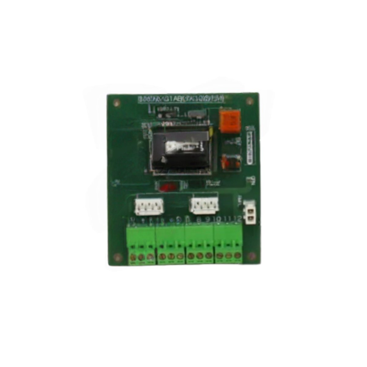
This contactor pilot board controls high-power contactors in GE drive systems. It provides relay outputs for energizing main circuit contactors and auxiliaries. The unit mounts inside the drive cabinet as a pilot control device.
Technical specifications
| Parameter | Specification |
|---|---|
| Brand | GE Energy |
| Model 1 | DS200CPCAG1A |
| Model 2 | DS200CPCAG1ABB |
| Product Family | Mark V / Drive Control |
| Category | Contactor Pilot Board |
| PCB Layer Count | 4 layers |
| Base Material | FR-4 flame retardant |
| Number of Relay Outputs | 8 (eight) Form A (NO) |
| Relay Contact Rating | 5A at 250V AC / 30V DC |
| Coil Voltage | 24V DC |
| Response Time | 15 ms typical (operate) |
| Input Control Signals | 24V DC from main controller |
| Status Indicators | 8 x LEDs (relay status), 2 x LEDs (PWR, RUN) |
| Component Count | Approximately 90 components |
| Integrated Circuits | 10 ICs (drivers, optocouplers) |
| Connector Types | 2 x 20-pin headers, 1 x terminal block |
| Power Supply | 24V DC external |
| Current Consumption | 120 mA (logic) + coil current |
| Test Points | 6 gold-plated test points |
| Energy Storage | None (no battery or capacitor) |
| Dimensions (L x W) | Approx. 22 cm x 14 cm |
| Thickness | Approx. 1.6 mm |
| Weight | Approx. 0.28 kg |
| Operating Temperature | 0°C to 55°C |
| Mounting | 4 x screw holes (M4) |
Detailed Technical Analysis
This contactor pilot board provides eight relay outputs for switching high-power contactors. Each relay handles 5 amps at 250V AC for main circuit control. The board receives 24V DC control signals from the main drive controller. Each relay has a dedicated LED to show its energization status.
Now let us examine its output characteristics. The relays switch within 15 milliseconds for rapid contactor response. The board draws 120 milliamps for its internal logic circuits. The relay coils draw additional current from the same 24V supply. Approximately 90 components populate both sides of this 4-layer PCB.
This pilot board contains no batteries or capacitors for energy storage. Two LEDs indicate power and run status for the entire board. Six gold-plated test points allow signal verification during commissioning. The GE DS200CPCAG1A DS200CPCAG1ABB mounts securely with four M4 screws.
Installation and Connection Guidelines
You mount this board using four M4 screws with insulating standoffs. Connect the 24V DC power supply to the designated terminal block. Wire each contactor coil to its corresponding relay output terminal. Connect control signals from the main controller to the input header.
Use proper suppression devices across contactor coils to reduce electrical noise. The board requires no configuration jumpers or software setup. Verify each relay operation before placing the drive into service. Always power down the drive before inserting or removing this board.
Practical Applications
Engineers use this pilot board for GE drive repair and contactor control. It switches main circuit contactors and auxiliary devices. This component also works in legacy drive upgrade projects. Its eight relay outputs suit complex contactor sequencing requirements.
Summary of Features
To conclude, this contactor pilot board provides 8 relay outputs at 5 amps each. It weighs 0.28 kilograms and draws 120 milliamps at 24V. Choose DS200CPCAG1A DS200CPCAG1ABB for reliable contactor control in drive systems.
Details
| Weight | 0.1 kg |
|---|---|
| Dimensions | 25 × 108 × 127 mm |
Reviews
There are no reviews yet.