
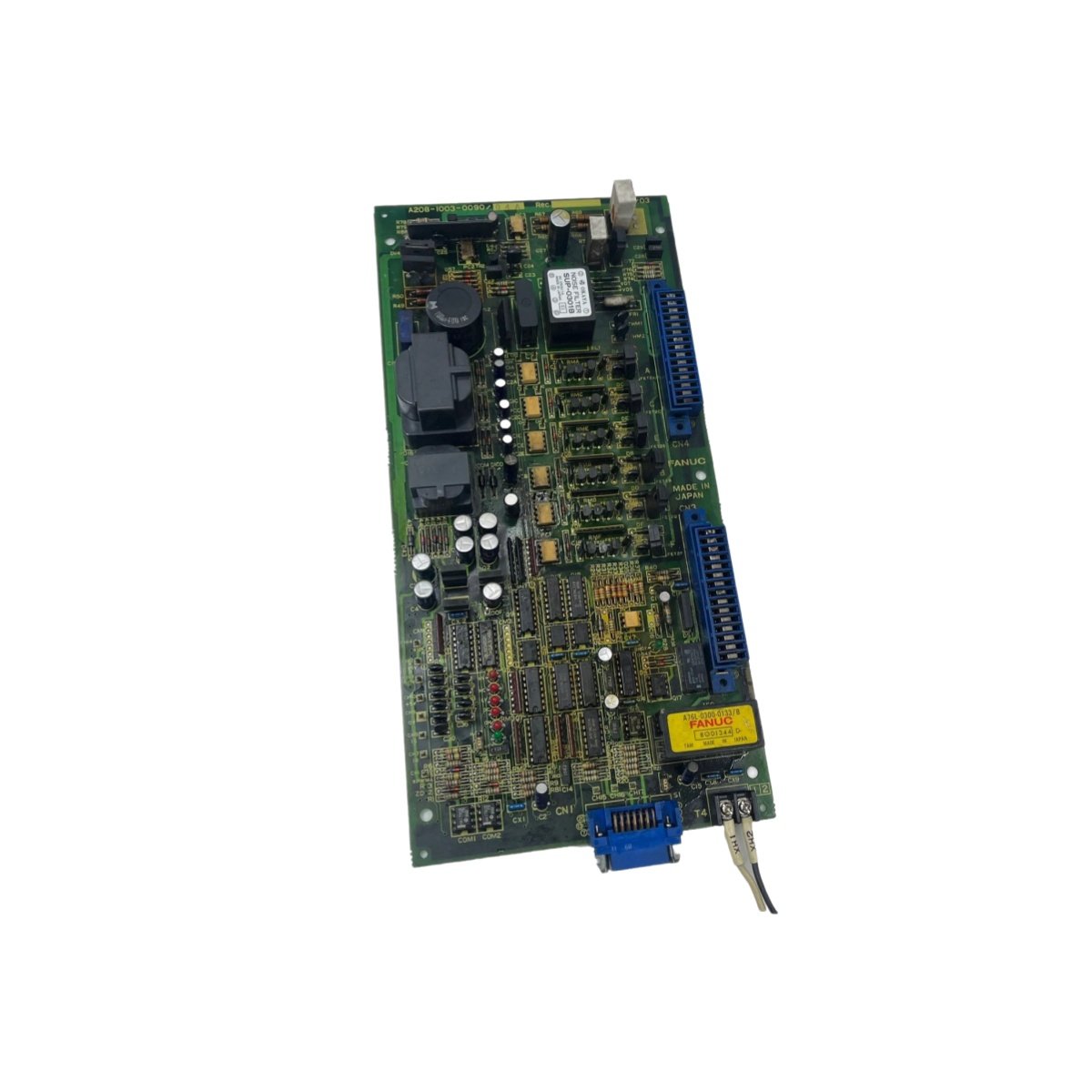
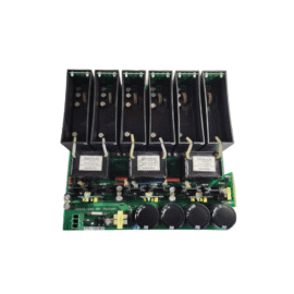
The GE A20B-I003-0090/04A servo drive top board functions as the primary control interface within compatible servo amplifier assemblies. This printed circuit board processes velocity and position commands from the CNC controller. The GE A20B-I003-0090/04A also monitors actual motor feedback through resolver or encoder connections. Its dedicated digital signal processor executes servo control algorithms with exceptional precision. The top board interfaces directly with the power stage through a high-density connector array. This design ensures reliable signal transfer between the control section and the power section.
PCB Architecture and Component Configuration
The GE A20B-I003-0090/04A contains a main processor, memory ICs, and several proprietary gate array chips. The PCB uses a multi-layer design to minimize noise coupling between high-speed digital traces. The board includes a 32-bit RISC processor operating at 40 MHz for real-time control loops. The A20B-I003-0090/04A incorporates 512 KB of SRAM for storing control parameters and tuning constants. A separate 256 KB of flash memory retains the firmware and configuration data. The board also features a battery-backed real-time clock for maintaining absolute position data. The PCB dimensions measure 7.5 inches in length and 5.0 inches in width. The GE A20B-I003-0090/04A weighs approximately 0.5 pounds with its mounting hardware.
The board utilizes a 96-pin DIN connector for interfacing with the power amplifier module. Two additional 20-pin ribbon connectors provide communication with external encoders and resolvers. The A20B-I003-0090/04A also includes test points for monitoring key internal signals during troubleshooting. Its surface-mount construction maximizes component density while maintaining service accessibility.
Functional Performance and Operational Characteristics
The GE supports velocity loop update rates up to 4 kHz for responsive motion control. The board accepts analog command signals from -10V to +10V for velocity and torque control modes. It also handles digital commands via high-speed serial communication links. The A20B-I003-0090/04A generates PWM signals at 8 kHz switching frequency for the power transistors. The board includes overcurrent and overspeed detection circuits to protect the servo motor. Its internal temperature sensor triggers a warning above 65 degrees Celsius for proactive thermal management.
Comprehensive Technical Specifications Table
| Parameter | Specification |
|---|---|
| Part Number | A20B-I003-0090/04A |
| Board Type | Servo Drive Top Board (Control Board) |
| Processor | 32-bit RISC @ 40 MHz |
| SRAM | 512 KB |
| Flash Memory | 256 KB |
| Real-Time Clock | Yes (battery-backed) |
| Command Input | ±10V analog or serial digital |
| Velocity Loop Update | Up to 4 kHz |
| PWM Switching Frequency | 8 kHz |
| Connectors | 96-pin DIN, 2 x 20-pin ribbon |
| PCB Dimensions (L x W) | 7.5 x 5.0 inches |
| Weight | 0.5 lbs |
| Operating Temperature | 0 to 55°C |
| Storage Temperature | -20 to 85°C |
| Test Points | 12 (signal monitoring) |
Application Integration and Replacement Guidance
The GE directly replaces earlier revisions in existing CNC servo drives. This top board supports both AC and DC servo motor configurations with proper parameter settings. The A20B-I003-0090/04A coordinates with the feedback board for precise position and speed regulation. Its firmware accommodates various motor types including brushless AC and DC motors. The GE serves as the intelligent heart of the servo amplifier system. Proper electrostatic discharge precautions are essential when handling this sensitive electronic board.
Details
| Weight | 0.20 kg |
|---|---|
| Dimensions | 108 × 85 × 50 mm |
Reviews
There are no reviews yet.