
Hardware Overview
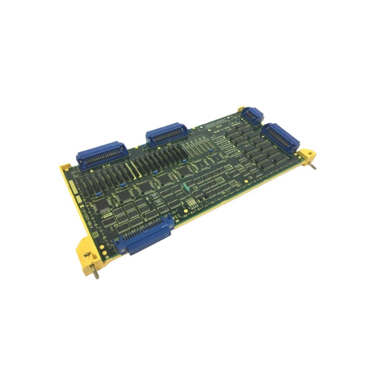
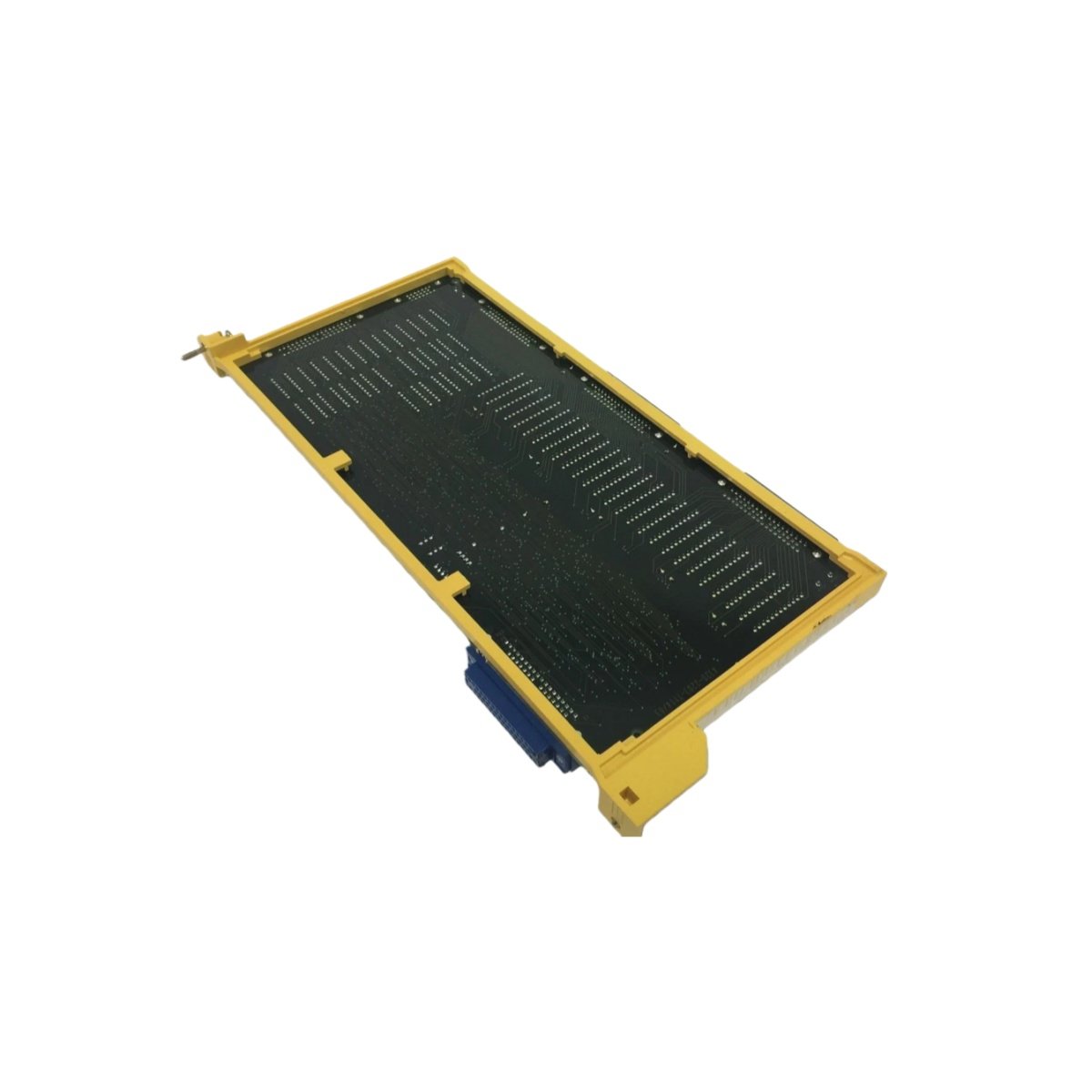
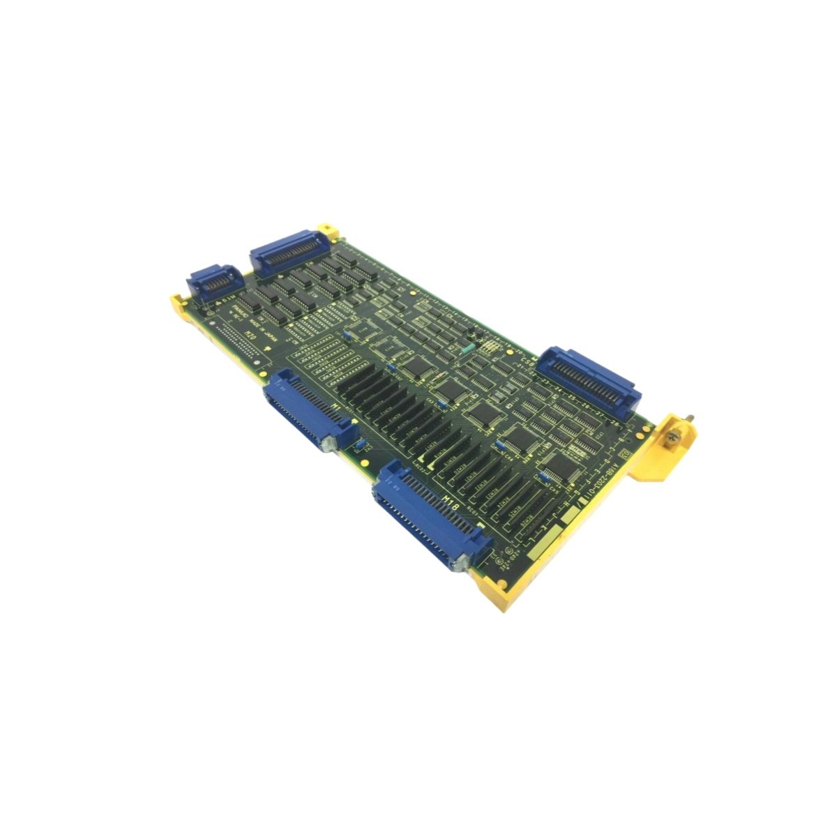
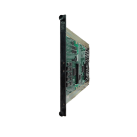
The GE A16B-2203-0111 operates as a multifunctional PC board within the Mark I series control systems. This board manages signal conditioning and interface functions for various I/O modules. It provides the necessary isolation between field signals and the main processor. Many legacy turbine control installations still rely on this robust platform.
Technical Specifications
The A16B-2203-0111 measures 300 mm in length and 200 mm in width. Its larger PCB footprint accommodates extensive circuitry. The board weighs approximately 1.1 kilograms. It operates on a +5V DC supply with a peak current draw of 2.0 A.
| Parameter | Specification |
|---|---|
| Model | A16B-2203-0111 |
| Product Type | PC Board / Interface Board |
| Dimensions | 300 mm x 200 mm |
| Weight | ~1.1 kg |
| Operating Voltage | +5V DC |
| Current Draw | 2.0 A (peak) |
| Connector Types | 2 x 50-pin ribbon, 3 x 20-pin headers |
| On-board Components | 4 op-amps, 8 optocouplers, 1 voltage regulator |
| Signal Channels | 16 differential analog inputs |
| Isolation Type | Optical (2500 VAC) |
| Energy Storage | 100 μF tantalum capacitor array |
| LED Indicators | 1 x Power, 2 x Status (red/green) |
| Operating Temp. | 0°C to +55°C |
Signal Processing and Interface Design
This board processes sixteen differential analog input channels for accurate signal acquisition. Each channel uses a dedicated operational amplifier for conditioning. Eight optocouplers provide optical isolation between the field and logic sides. This isolation reaches 2500 VAC for robust protection. The board features two 50-pin ribbon connectors for field wiring interfaces. Three 20-pin headers connect to internal system buses. A single voltage regulator ensures stable +5V power for all onboard components. The design prioritizes signal integrity in high-noise environments.
Component Architecture and Energy Storage
The GE A16B-2203-0111 incorporates four high-precision op-amps for signal amplification. These op-amps deliver low offset and drift characteristics. Eight high-speed optocouplers handle digital signal isolation tasks. A tantalum capacitor array provides 100 μF of distributed energy storage. This capacitance maintains stable operation during brief power dips. The board uses a +5V supply only, simplifying power distribution. Its larger size accommodates the dense component placement.
Installation and Compatibility
Installing the A16B-2203-0111 requires a standard Mark I rack slot with sufficient depth. The board connects to the backplane via its edge connector. Field wiring terminates at the ribbon cable headers. Three LED indicators show power and dual-channel status. The module functions reliably across 0°C to 55°C ambient temperatures. This board serves as a direct replacement for earlier revision boards. Check compatibility with your specific Mark I system variant.
Reliability and Service Considerations
The A16B-2203-0111 employs industrial-grade components for long-term durability. The optocouplers eliminate electrical path failures between circuits. Tantalum capacitors offer stable capacitance over temperature extremes. Regular inspection of LED status indicators helps detect anomalies early. Board replacement requires standard ESD precautions and basic tools.
Details
| Weight | 1.1 kg |
|---|---|
| Dimensions | 300 × 200 × 5 mm |
Reviews
There are no reviews yet.