
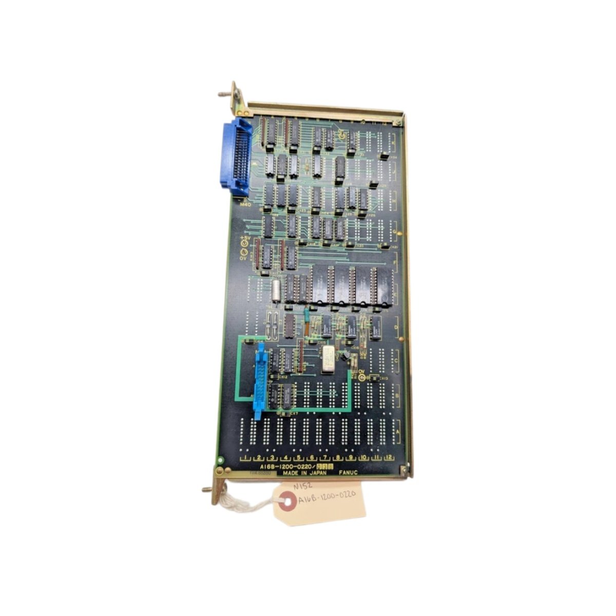
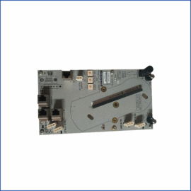
This GE Fanuc interface board manages signal routing between CNC controllers and machine tools. It handles discrete I/O, analog signals, and encoder feedback for precision applications. Engineers can trust this unit for consistent performance in high-speed machining environments. Its multi-layer PCB design ensures reliable signal integrity and noise immunity. The board supports various machine configurations through flexible interface options.
Physical Dimensions and Board Layout
The interface board measures 11.0 inches in length and 8.5 inches in height. Its four-layer PCB weighs approximately 1.2 pounds for straightforward handling. The board includes 4 mounting holes for secure attachment to chassis plates. A 96-pin DIN connector establishes all communication with the main controller. This connector arrangement simplifies cable routing and reduces wiring complexity significantly.
Component Architecture and Processing Capability
The board integrates a main microprocessor and two dedicated ASIC devices. It also incorporates 8 opto-isolated input channels for digital signal detection. The unit provides 8 relay output channels for driving external actuators. A 1 MB DRAM buffer stores interpolation data and tool path coordinates. This memory capacity accommodates complex machining programs without performance degradation.
Interface Protocols and Communication Standards
The module communicates via the high-speed FANUC serial bus at 2 Mbps. This bus exchanges real-time data with servo amplifiers and spindle drives. The board also supports RS-422 differential signaling for long-distance connections. A dedicated analog output provides ±10 VDC signals for spindle speed control. These communication options ensure seamless integration with diverse machine components.
Power Supply Requirements and Current Draw
The board draws 500 mA from the +5 VDC logic supply rail. It also requires 200 mA from the ±15 VDC analog supply for signal conditioning. Total power consumption reaches approximately 8 watts under typical operating conditions. An onboard switching regulator maintains stable voltage for all IC components. This regulator minimizes heat generation and improves overall power efficiency.
Diagnostic Monitoring and Fault Detection
The interface board features 4 diagnostic LEDs for real-time status verification. These indicators display power, communication, and error conditions clearly. The unit performs continuous self-diagnostics on all input and output channels. It reports fault conditions to the CNC through dedicated status registers. This monitoring capability reduces machine downtime and simplifies fault finding procedures.
Environmental Resilience and Operating Parameters
The board operates reliably from 0 to 55 degrees Celsius ambient temperature. Its conformal coating protects circuit traces from moisture and dust accumulation. The unit withstands non-condensing humidity levels up to 90% for factory deployment. Gold-plated edge connectors resist corrosion and maintain signal quality over time. This robust construction ensures long-term reliability in harsh machine shop environments.
Technical Specifications Overview
| Parameter | Detail |
|---|---|
| Model Number | A16B-1212-0210/10B |
| Board Type | Interface Board |
| Input Channels | 8 opto-isolated DC inputs |
| Output Channels | 8 relay outputs |
| Analog Output | ±10 VDC (1 channel) |
| Communication | FANUC serial bus (2 Mbps), RS-422 |
| DRAM Buffer | 1 MB |
| Logic Supply | 500 mA at +5 VDC |
| Analog Supply | 200 mA at ±15 VDC |
| Power Dissipation | 8 W |
| Connector | 96-pin DIN |
| PCB Layers | 4 layers |
| Dimensions | 11.0 x 8.5 inches |
| Weight | 1.2 lbs |
| Operating Temperature | 0 to 55 °C |
Details
| Weight | 0.65 kg |
|---|---|
| Dimensions | 140 × 110 × 75 mm |
Reviews
There are no reviews yet.