
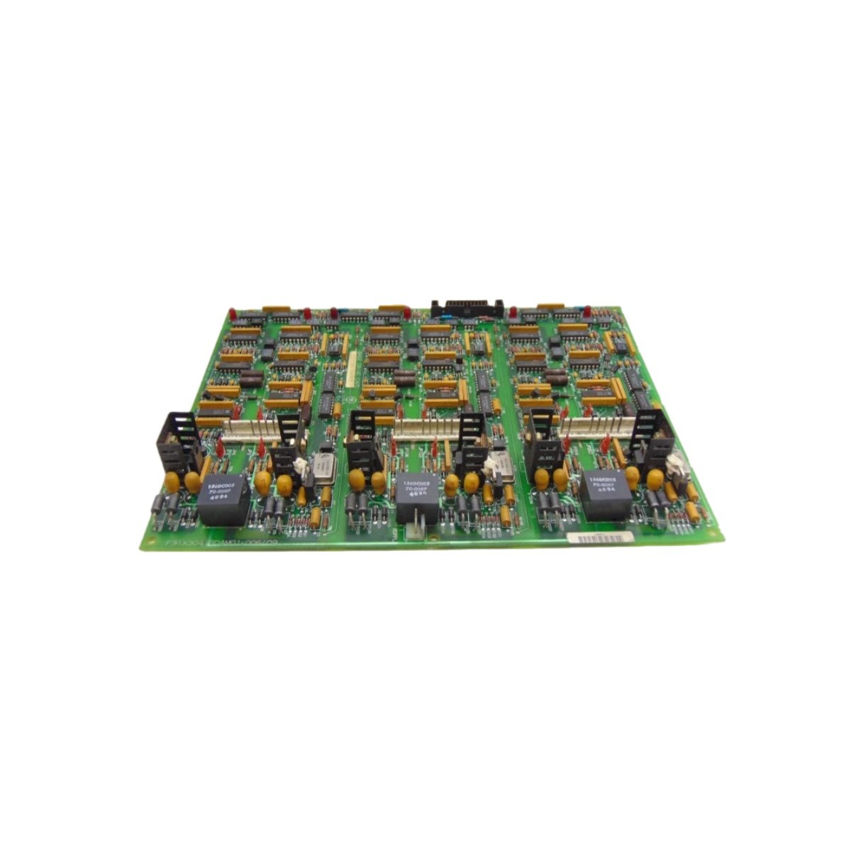
This base drive board provides critical interface functions for GE DC drive systems. The GE 531X304IBDANG1 F31X304IBDAMG1 manages power conversion and feedback control. It interfaces directly with the main drive controller and power semiconductor assemblies. The board generates PWM gate signals for SCR or IGBT firing circuits. Its comprehensive protection features safeguard the drive system against overcurrent and overtemperature faults.
Mechanical Dimensions and Construction Quality
The board measures 310 mm in height, 165 mm in width, and 2.5 mm in thickness. This extended form factor accommodates high-voltage isolation components and large terminals. Weighing approximately 0.78 kg, the 531X304IBDANG1 F31X304IBDAMG1 provides rugged mechanical stability. The FR-4 substrate meets high-temperature requirements with a UL 94 V-0 rating. A factory-applied conformal coating protects against moisture, dust, and chemical exposure.
Technical Specifications at a Glance
| Specification | Detail |
|---|---|
| Board Type | Base drive / gate interface |
| Drive Compatibility | GE DC drive systems |
| Gate Signal Outputs | 6 (phase-controlled) |
| Feedback Inputs | Armature voltage, tachometer, current |
| Protection Features | Overcurrent, overtemperature, undervoltage |
| Dimensions (H × W × T) | 310 mm × 165 mm × 2.5 mm |
| Weight | 0.78 kg |
| Connectors | 2 x 64-pin headers, 1 x 10-pin ribbon |
| Terminal Blocks | 6-position screw clamp (AC input) |
| Backplane Supply | ±15 VDC, 24 VDC |
| Power Consumption | 7.5 W |
| Gate Drive Voltage | +15 VDC / -5 VDC (regulated) |
| Isolation Voltage | 2500 VAC (optical) |
| Energy Buffer | 150 µF (bulk capacitance) |
| Temperature Range | -25 °C to +65 °C |
| Humidity Range | 5% – 95% RH (non-condensing) |
| Standards | UL 508, CSA, CE, RoHS |
| Component Count | 280 resistors, 175 capacitors, 22 ICs, 6 gate-drive transformers |
Interface and Connectivity Features
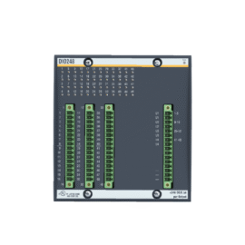
Two 64-pin headers provide the primary interface to the main drive controller. A 6-position screw terminal block accepts AC power input for the internal supplies. The board also includes a 10-pin ribbon connector for auxiliary signal interfacing. Test points on the board allow direct measurement of gate signals and feedback values. LED indicators display board status, gate enable, and fault conditions clearly.
Power Architecture and Energy Storage
The GE 531X304IBDANG1 F31X304IBDAMG1 draws power from the ±15 VDC and 24 VDC backplane supplies. It regulates these voltages internally for gate drive and logic circuits. A 150 µF bulk capacitor provides local energy storage for transient ride-through. This capacitor supports gate firing during momentary power interruptions. Total power dissipation measures 7.5 W under normal operating conditions.
Internal Component Architecture
Six isolated gate-drive transformers couple PWM signals from the logic side to the power side. Each channel uses optocoupler isolation for 2500 VAC dielectric strength. The board includes pulse-shaping circuits for precise gate control signals. A 280 surface-mount resistors and 175 ceramic capacitors populate the PCB. Twenty-two integrated circuits include gate drivers, comparators, and voltage references. The board also integrates overcurrent sensing circuits for each phase.
Environmental Performance and Certifications
This base drive board operates reliably from -25 °C to +65 °C in drive cabinet environments. It also withstands humidity levels between 5% and 95% without condensation. The 531X304IBDANG1 complies with UL 508, CSA, CE, and RoHS standards. These certifications ensure safe integration into GE DC drive systems.
Details
| Weight | 0.78 kg |
|---|---|
| Dimensions | 310 × 165 × 2.5 mm |
Reviews
There are no reviews yet.