Technical Specifications and Board Design
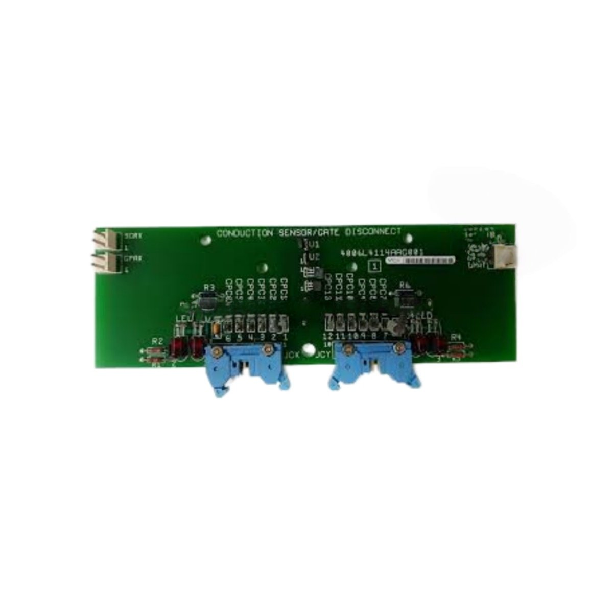
This conduction sensor gate disconnect PCB monitors power semiconductor health in GE drive systems. The GE 4006L4114AAG001 detects gate drive failures and initiates protective shutdowns. You can install this board into any standard Mark V or DC drive rack slot. Its high-voltage isolation circuitry protects low-voltage logic from power stage faults. The board weighs approximately 0.48 kilograms. Its dimensions measure 24 cm in height, 16 cm in width, and 2 cm in depth.
| Parameter | Specification |
|---|---|
| Brand | GE Energy / General Electric |
| Model | 4006L4114AAG001 |
| Category | Conduction Sensor Gate Disconnect PCB / Protection Circuit Board |
| Weight | 0.48 kg |
| Height | 24 cm |
| Width | 16 cm |
| Depth | 2 cm |
| Number of Sensor Channels | 6 independent conduction sensor channels |
| Gate Disconnect Outputs | 6 channels (24V DC, 0.5A) |
| Input Voltage Range | 5-30V DC (sensor supply) |
| Detection Threshold | Programmable (1-10V drop) |
| Response Time | 2 microseconds typical |
| Isolation Voltage | 3500V DC between power and logic |
| Status Indicators | 6 red LEDs (fault per channel) |
| Backplane Interface | 32-pin edge connector |
| Energy Storage | None (no battery) |
| Component Count | Single PCB with comparators, optocouplers, and gate drivers |
Conduction Sensing and Gate Monitoring
The board continuously monitors voltage drop across each power semiconductor. A sudden increase in drop indicates a gate drive failure. The GE 4006L4114AAG001 compares each channel against a programmable threshold. It triggers a gate disconnect signal within 2 microseconds of detecting a fault. This rapid response prevents short circuits through failed devices. The board provides optical isolation between each sensor channel. Consequently, a fault on one channel does not affect others. A red LED illuminates on any channel where a fault occurs.
Gate Disconnect Function and Protection Logic
Upon detecting a fault, the board opens the gate disconnect circuit immediately. This action removes the gate drive signal from the faulty semiconductor. The GE 4006L4114AAG001 latches the fault state until you manually reset it. A remote reset input allows controller-based fault clearing. The board also reports fault status back to the main system via the backplane. Each disconnect output can drive external gate driver enable circuits. The board defaults to a safe disconnected state during power loss.
Installation and Operational Guidelines
You must insert this board into a slot near the power semiconductor modules. The backplane supplies 5V and 24V DC power to the board automatically. The GE 4006L4114AAG001 draws approximately 150 mA from the 5V supply rail. It draws an additional 100 mA from the 24V supply for disconnect outputs. You must use twisted-pair wiring for all conduction sensor connections. This practice prevents noise from causing false fault detections. The board requires no external battery for normal operation. You should test each channel periodically to verify threshold accuracy.
Details
| Weight | 0.45 kg |
|---|---|
| Dimensions | 170 × 145 × 65 mm |
Reviews
There are no reviews yet.