Key Technical Specifications
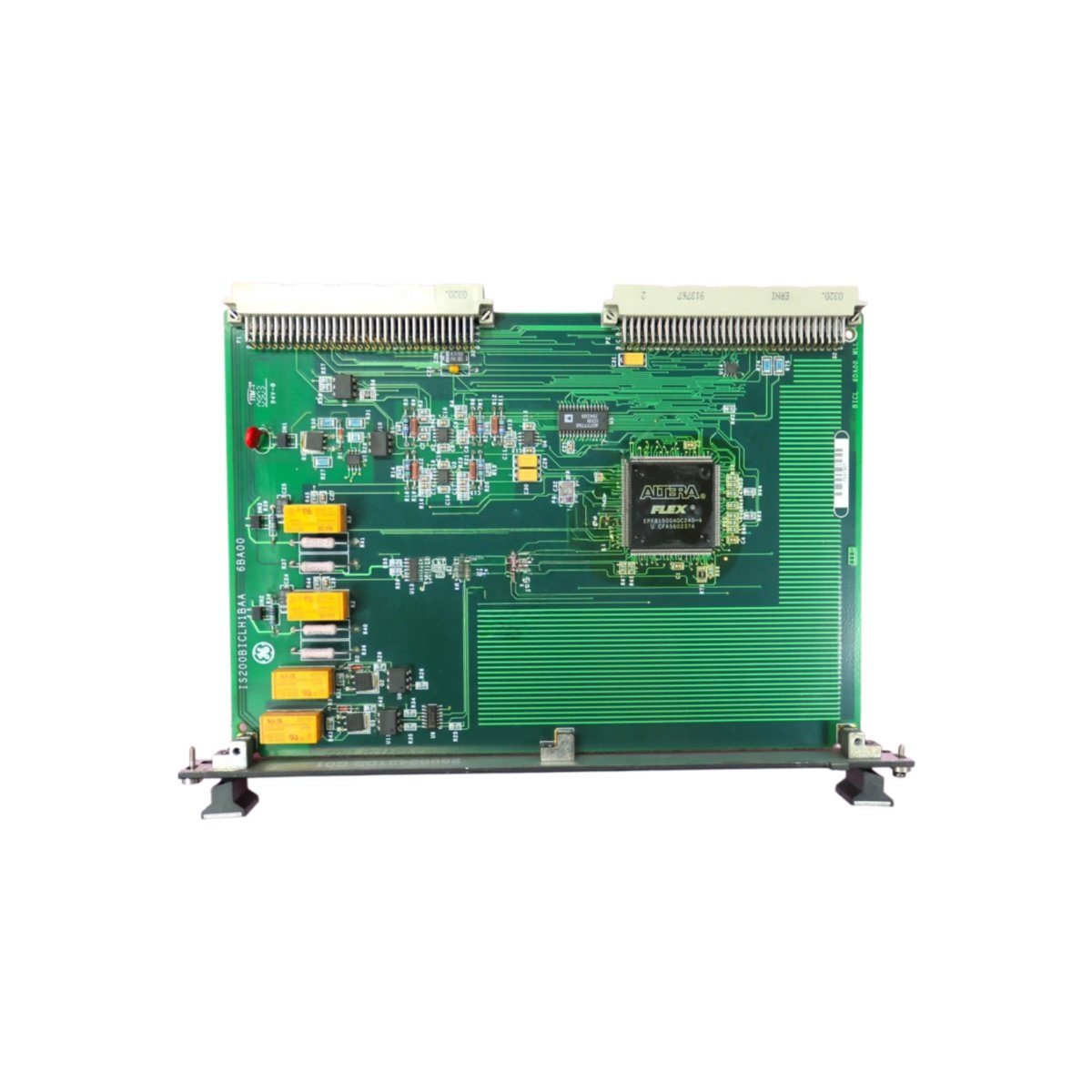
This GE 151X1233DD01SA02 IS200AEPBH1BAA 109W6931P001 board accepts 240V AC single-phase input power. It delivers 5A charging current for 125V DC battery systems. The unit measures 28 cm in length, 20 cm in width, and 6 cm in height. Its total weight reaches 1.2 kg without any packaging materials.
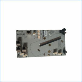
The GE 151X1233DD01SA02 IS200AEPBH1BAA includes one rectifier bridge and one charge controller. Additionally, it features one input fuse holder and one output circuit breaker. A single 6-pin terminal block connects the AC input and DC output. The board contains 1 rectifier, 1 controller IC, 1 transformer, 2 fuses, 1 breaker, 4 status LEDs, 10 capacitors, and 16 resistors.
| Parameter | Value |
|---|---|
| Input Voltage | 240V AC ±10%, 50/60Hz |
| Output Voltage | 125V DC nominal |
| Charging Current | 5A continuous |
| Battery Capacity | Up to 150 Ah |
| Dimensions (L x W x H) | 28 cm x 20 cm x 6 cm |
| Weight | 1.2 kg |
| Charging Mode | Float and boost |
| Float Voltage | 130V DC ±1% |
| Boost Voltage | 140V DC ±1% |
| Input Fuse | 8A, slow-blow |
| Output Breaker | 5A, magnetic |
| Power Connector | 6-pin terminal block |
| Rectifier Bridge | 1 unit (15A, 400V) |
| Controller IC | 1 unit |
| Transformer | 1 unit (400VA) |
| Status LEDs | 4 units (Power, Float, Boost, Fault) |
| Capacitors | 10 units (filtering) |
| Resistors | 16 units |
| Energy Storage | 1500 µF at 250V |
GE 151X1233DD01SA02 IS200AEPBH1BAA stores energy using two electrolytic capacitors. Together, they provide 1500 µF at 250V rating for output filtering. This energy storage maintains DC output during 25 millisecond AC interruptions. Therefore, the board provides continuous power to loads during brief sags.
Design and Integration
Both the GE 151X1233DD01SA02 and IS200AEPBH1BAA versions share identical charging circuitry. This board uses four-layer PCB construction with heavy copper for high current paths. Consequently, the GE 151X1233DD01SA02 IS200AEPBH1BAA operates reliably from -10°C to +50°C ambient temperature. The 109W6931P001 marking indicates GE manufacturing code.
For installation, you need M4 screws for the four mounting holes. The board draws 5A typical input current at full load. The charger automatically switches between float and boost modes. We recommend using 14 AWG wire for both input and output connections.
Practical Application
This battery charger board maintains station battery banks for turbine control systems. It provides regulated DC power to keep batteries fully charged. The GE 151X1233DD01SA02 IS200AEPBH1BAA also supplies control power directly to loads during normal operation. Therefore, it ensures backup power availability for GE turbine and generator protection systems.
Details
| Weight | 0.1 kg |
|---|---|
| Dimensions | 25 × 108 × 127 mm |
Reviews
There are no reviews yet.