
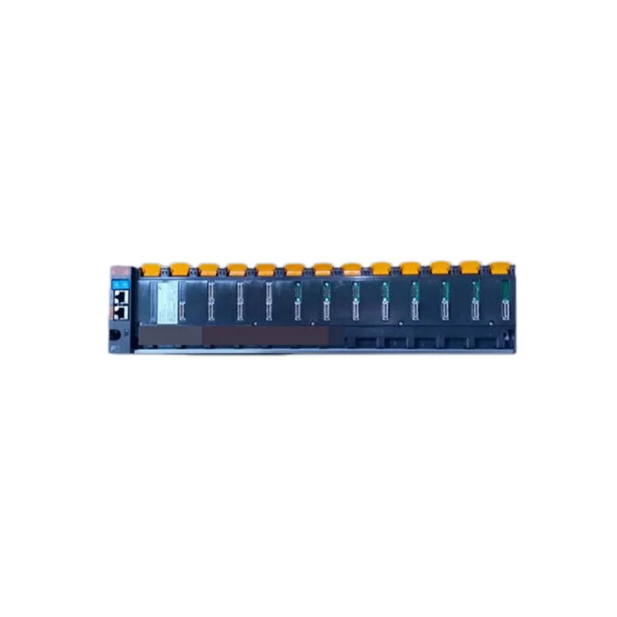
Modular Rack for Micro-SX System Assembly
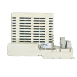
The FUJI NP1BS-13S base board provides the physical backbone for Micro-SX PLC configurations. This rack holds all I/O modules, power supplies, and communication processors in a structured layout. System integrators appreciate this board for its flexible slot allocation and reliable backplane connections.
Slot Configuration and Power Distribution
This base board features 13 slots arranged in a single row for module installation. The backplane provides both 5 V DC power and data communication to all connected modules. An integrated power supply connector accepts the main 24 V DC input. Furthermore, the board includes a bus extension connector for linking additional racks.
| Parameter | Specification |
|---|---|
| Brand | FUJI |
| Model | NP1BS-13S |
| Number of Slots | 13 |
| Power Supply Voltage | 24 V DC (nominal) |
| Backplane Current Capacity | 5 V DC at 8 A |
| Bus Extension | Yes (for additional racks) |
| Mounting Type | DIN rail or panel |
| Dimensions (W x H x D) | 330 mm x 100 mm x 80 mm |
| Weight | 1.20 kg |
| Compatible Modules | Micro-SX series |
| Operating Temperature | 0°C to 55°C |
| Storage Temperature | -20°C to +70°C |
Mechanical Design and Installation
The FUJI NP1BS-13S features a sturdy metal chassis with a protective coating for corrosion resistance. The board mounts easily on a standard 35 mm DIN rail or directly on a panel. Each slot includes guide rails for secure module insertion and retention. The housing also provides cable management channels for organized wiring.
Backplane Communication and Addressing
The backplane bus operates at a high speed, synchronizing all modules within the rack. The board automatically assigns slot addresses to each installed module. Users can mix input, output, and communication modules in any slot positions. Additionally, the bus extension connector allows you to link up to three base boards together.
Power Supply Integration and Protection
This base board includes a fuse holder for the main 24 V DC supply. An LED indicator shows the presence of backplane power. The board also features reverse polarity protection on the power input. For redundant configurations, you can connect two power supplies using external diodes.
Application Guidelines and System Configuration
You can assemble a complete Micro-SX system using this base board as the foundation. Install the CPU module in the first slot for proper bus arbitration. Place I/O modules in the remaining slots according to your process requirements. Always ensure the total backplane current does not exceed the 8 A rating. For multi-rack systems, connect the bus cables between boards and terminate the last rack.
Details
| Weight | 0.7 kg |
|---|---|
| Dimensions | 2.5 × 20.3 × 15.2 mm |
Reviews
There are no reviews yet.