
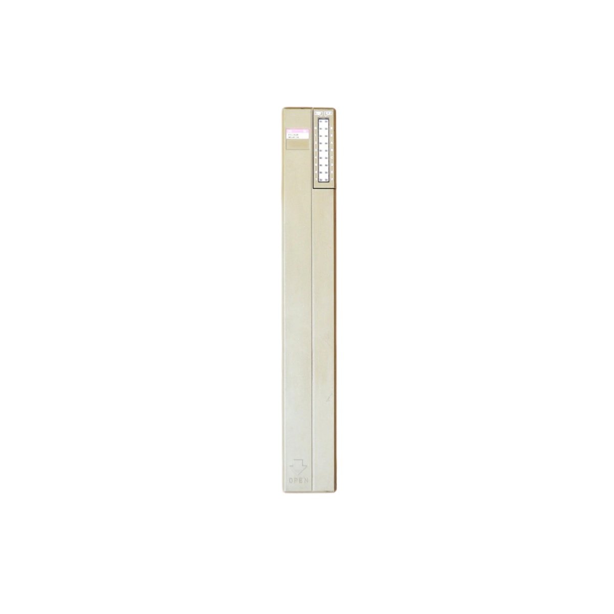
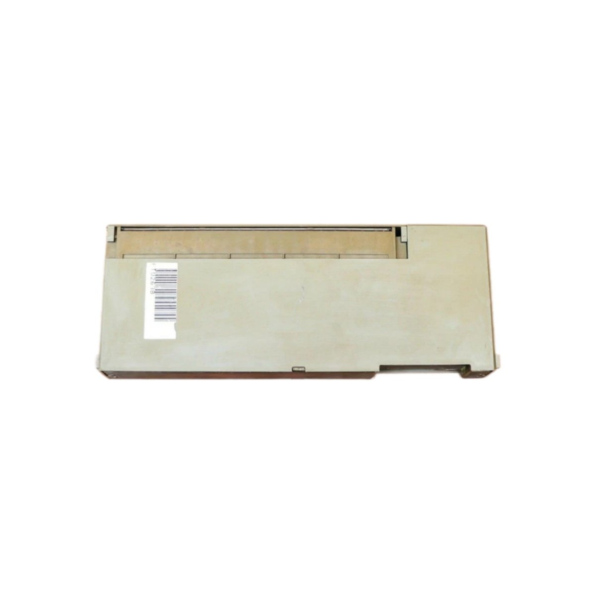
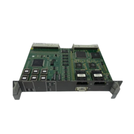
This digital output module drives actuators and indicators from PLC or DCS control signals. It translates logic-level commands into robust 24 V DC switching outputs. The device offers eight independent channels for flexible field device control.
Technical Specifications
| Parameter | Specification |
|---|---|
| Model Number | FTU263B |
| Product Type | Digital Output Module |
| Supply Voltage | 24 V DC ±20% |
| Power Consumption | 40 mA (internal logic) + load current |
| Number of Outputs | 8 (optically isolated) |
| Output Type | Transistor (NPN sinking) |
| Output Voltage | 24 V DC (nominal) |
| Output Current | 0.5 A per channel (continuous) |
| Total Current | 4 A (maximum, all channels combined) |
| Short-circuit Protection | Yes (per channel, electronic) |
| Overload Protection | Yes (thermal, per channel) |
| Inductive Load Clamping | Integrated flyback diode |
| Status Indicators | 8 x LED (green, per channel) |
| Connection | 18-pin spring-clamp terminal block |
| Mounting | DIN rail (TS 35) |
| Dimensions (W x H x D) | 38 mm x 100 mm x 75 mm |
| Weight | 0.18 kg |
Mechanical Construction and Installation
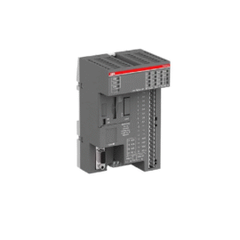
This module features a slim 38 mm wide housing for dense cabinet layouts. Its DIN-rail mounting mechanism allows for quick and secure installation. The unit weighs just 0.18 kilograms, placing minimal stress on the mounting rail. All connections use spring-clamp terminals for tool-free wiring.
Power Supply and Electrical Characteristics
The device operates from a standard 24 V DC supply with a ±20 percent tolerance. The internal logic consumes only 40 milliamperes of current. The field outputs draw additional current based on the connected loads. The module includes built-in reverse polarity protection for the supply input.
Output Configuration and Channel Isolation
Eight independent transistor outputs provide NPN sinking switching capability. Each channel delivers up to 0.5 amperes of continuous output current. The total combined output current across all channels must not exceed 4 amperes. Each output features optical isolation from the internal logic circuitry. This isolation prevents ground loops and protects the host controller.
Protection Mechanisms and Fault Tolerance
The module incorporates comprehensive protective features for each output channel. Electronic short-circuit protection limits current during accidental load faults. Thermal overload protection shuts down individual channels if they overheat. Integrated flyback diodes clamp inductive voltage spikes from relay coils. These safeguards ensure reliable operation in demanding industrial environments.
Diagnostic Feedback and Status Indication
Eight green LEDs display the real-time status of each output channel individually. An LED lights up whenever its corresponding channel is actively switched on. This visual feedback assists engineers during system commissioning. A single red LED indicates any module-level fault conditions.
Energy Storage and Transient Suppression
Internal capacitors provide noise filtering and transient suppression for the supply rail. These capacitors reduce voltage spikes from inductive load switching. The module also includes a small hold-up capacitor for brief supply interruptions. This capacitor maintains output states during sub-20-millisecond voltage dips.
Application Suitability
This output module suits a wide variety of discrete control applications. It works effectively with solenoid valves, contactors, and indicator lamps. The device also drives small motors, buzzers, and alarm annunciators. Its operating temperature range spans from -10°C to +55°C.
Details
| Weight | 1.4 kg |
|---|---|
| Dimensions | 127 × 254 × 203 mm |
Reviews
There are no reviews yet.