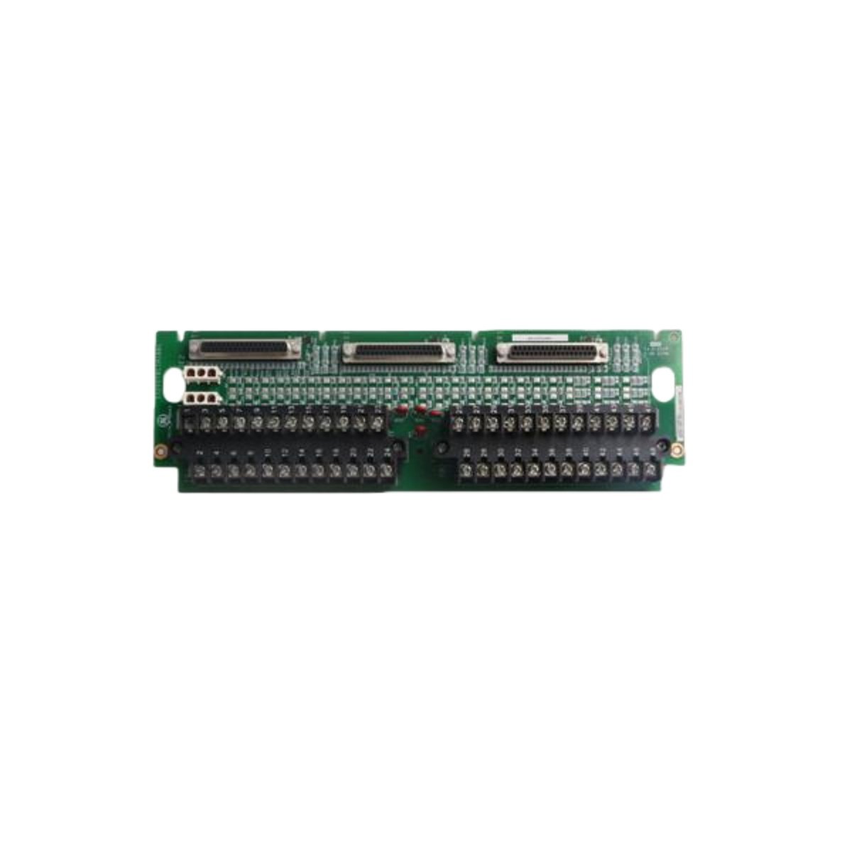
The GE IS200TBCIH1BBC IS200TBCIH1B serves as a dedicated contact input terminal board for turbine control applications. This printed circuit board interfaces directly with field contacts in Mark VI systems. It provides reliable signal conditioning for up to 48 individual contact inputs. The IS200TBCIH1B variant shares identical functionality and technical specifications with this model. Engineers use this board to connect limit switches, push buttons, and relay contacts securely.
Technical Specifications and Physical Characteristics
Accurate technical specifications enable proper installation of the GE IS200TBCIH1BBC IS200TBCIH1B in control cabinets. The board’s long, narrow design accommodates specific mounting requirements within turbine panels.
| Specification | Details |
|---|---|
| Product Type | Contact Input Terminal Board |
| Series | GE Mark VI Speedtronic |
| Compatible Systems | Gas and Steam Turbine Control Systems |
| PCB Format | Long, Narrow Printed Circuit Board |
| Mounting Type | Panel Mount (Not VME Rack Mountable) |
| Terminal Blocks | 2 Large Black Terminal Blocks (TB1, TB2) |
| Total Terminals | 48 Positions (Numbered 1 through 48) |
| Connector Ports | 3 Connector Ports along Right Edge |
| Auxiliary Connectors | 2 White Connectors at Top Center |
| Capacitors | 4 Round Red Capacitors |
| Semiconductor Count | Multiple Small Diodes and Capacitors in Central Array |
| Board Length | Approximately 350 mm |
| Board Height | Approximately 100 mm |
| Weight | 0.35 kg |
| Energy Storage Components | Filter capacitors for signal debouncing |
| Dielectric Withstand | 1500 Vdc isolation between field and logic |
| Operating Temperature | -30°C to +65°C |
Detailed Component Layout and Function
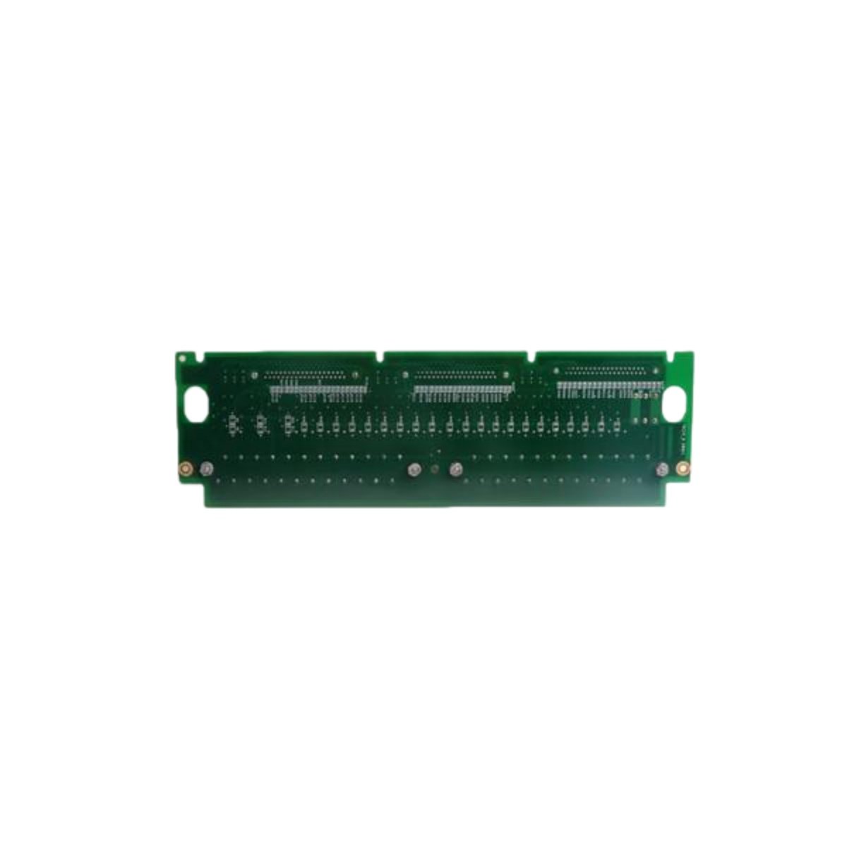
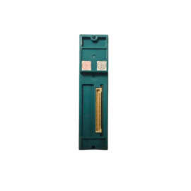
The IS200TBCIH1BBC IS200TBCIH1B contains carefully arranged components for optimal signal processing. Two large black terminal blocks dominate the board’s upper and lower sections. TB1 and TB2 each accommodate 24 field wiring connections for contact inputs. Three connector ports along the right edge interface with the main control system. Two additional white connectors at the top center provide auxiliary signal routing. The central area contains an array of small diodes and filtering capacitors. Four prominent round red capacitors provide energy storage for signal stability.
Installation Considerations and Physical Design
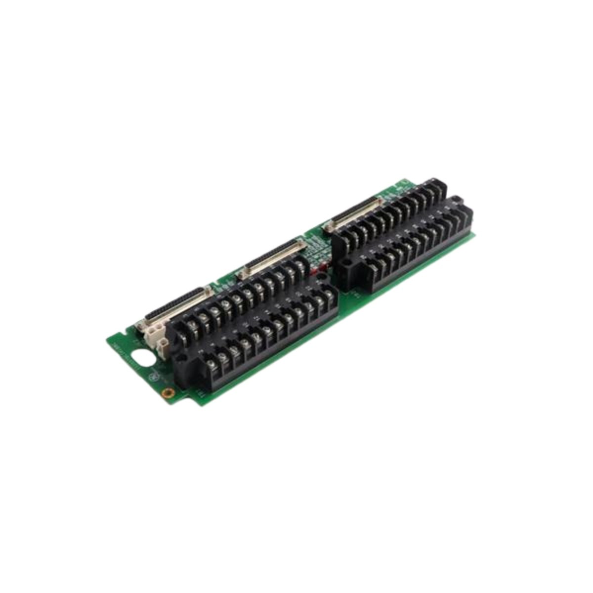
Engineers must handle the GE IS200TBCIH1BBC IS200TBCIH1B with care due to its fragile PCB construction. The long, narrow board lacks the rigidity of shorter circuit boards. This board does not include an exterior front faceplate for standard rack mounting. It cannot install in the typical VME Rack Mounting Assembly found in other systems. Proper mounting requires dedicated panel space with appropriate standoffs. The board’s design prioritizes signal density over mechanical ruggedness. Installers should use caution when wiring field connections to prevent board flexing.
Compatibility and System Integration
The IS200TBCIH1BBC IS200TBCIH1B functions within GE Mark VI turbine control architectures effectively. It represents an evolution from earlier Mark V designs while maintaining core functionality. Similar to protection devices like the RMS TSG TZ C Static Trip unit, this board ensures reliable signal acquisition. The 48 contact inputs connect directly to field devices without intermediate electronics. Each input passes through conditioning circuits for noise rejection and debouncing. The board communicates with the main controller through the edge connectors. This design allows the Mark VI system to monitor vast numbers of field contacts efficiently.
Application in Turbine Control Systems
The IS200TBCIH1B plays a vital role in monitoring turbine auxiliary equipment status. Common applications include valve position indication, pump run status, and alarm monitoring. Contact inputs from protective devices connect directly to this terminal board. The board’s filtering components prevent false triggering from electrical noise. Its compact component arrangement maximizes I/O density in space-constrained panels. Engineers appreciate the straightforward terminal numbering for simplified wiring and troubleshooting.
Details
| Weight | 0.1 kg |
|---|---|
| Dimensions | 25 × 108 × 127 mm |
Reviews
There are no reviews yet.