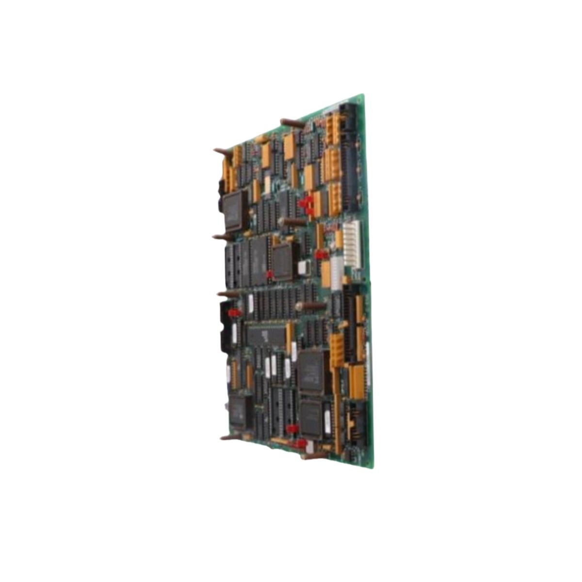
Industrial drive systems require stable and precise control boards. The GE DS200LDCCH1ALA DS200LDCCH1 delivers reliable logic processing for DC motor drives. This board functions as an LDCCH series circuit board from GE. It serves as a critical component in DC drive control cabinets.
Technical Specifications & Dimensions
This board handles both logic signals and power regulation tasks. The table below outlines its core technical parameters.
| Parameter | Specification |
|---|---|
| Board Type | Multi-layer PCB with surface mount components |
| Logic Supply | 24V DC ±10% |
| Analog Inputs | 4 channels (0-10V or 4-20mA) |
| Analog Outputs | 2 channels (0-10V) |
| Digital Inputs | 8 channels, 24V DC |
| Digital Outputs | 4 channels, relay or open collector |
| Power Consumption | 250 mA typical at 24V DC |
| Unit Weight | 0.38 kg (0.84 lbs) |
| Board Dimensions | 210 x 150 x 18 mm |
| Number of Components | 6 ICs + 22 capacitors + 35 resistors |
Construction and Interface Layout
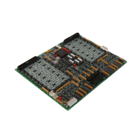
This board features a fiberglass epoxy substrate with gold-plated edge fingers. Such a design ensures reliable contact with the backplane connector. Furthermore, the GE DS200LDCCH1ALA provides multiple interface points for field wiring. You will find one 50-pin header and two 20-pin connectors on this board. The PCB also includes test points for diagnostic measurements. An LED cluster shows power and fault status clearly.
Energy Storage and Power Regulation
Unlike simple logic boards, this LDCCH card includes bulk capacitors for voltage smoothing. The board uses a bank of four 470µF capacitors for energy storage. Consequently, the GE DS200LDCCH1 maintains stable voltage during transient load changes. A dedicated switching regulator converts the 24V input to 5V logic power. This regulator achieves 85% efficiency under normal operating conditions. The board does not contain any user-replaceable batteries.
Installation and Mounting Requirements
Installing the GE DS200LDCCH1ALA DS200LDCCH1 requires careful alignment with the backplane slots. The board slides into a dedicated card cage within the drive cabinet. It also locks securely with top and bottom retaining clips. Always disconnect main power before inserting or removing this PCB. The unit uses passive cooling through natural air circulation. This design eliminates fan noise and mechanical failures. The board occupies a single slot in the card rack.
Integration with Drive Control Systems
This PCB works seamlessly with GE DC2000 and DC300 drive systems. It processes feedback signals from tachometers and encoders. Operators can monitor board status through diagnostic LEDs and test points. The GE DS200LDCCH1 also communicates with the main drive processor via a serial link. Consequently, this board remains essential for legacy drive repairs. The unit delivers consistent performance across a 0°C to 50°C temperature range.
Details
| Weight | 0.1 kg |
|---|---|
| Dimensions | 25 × 108 × 127 mm |
Reviews
There are no reviews yet.