
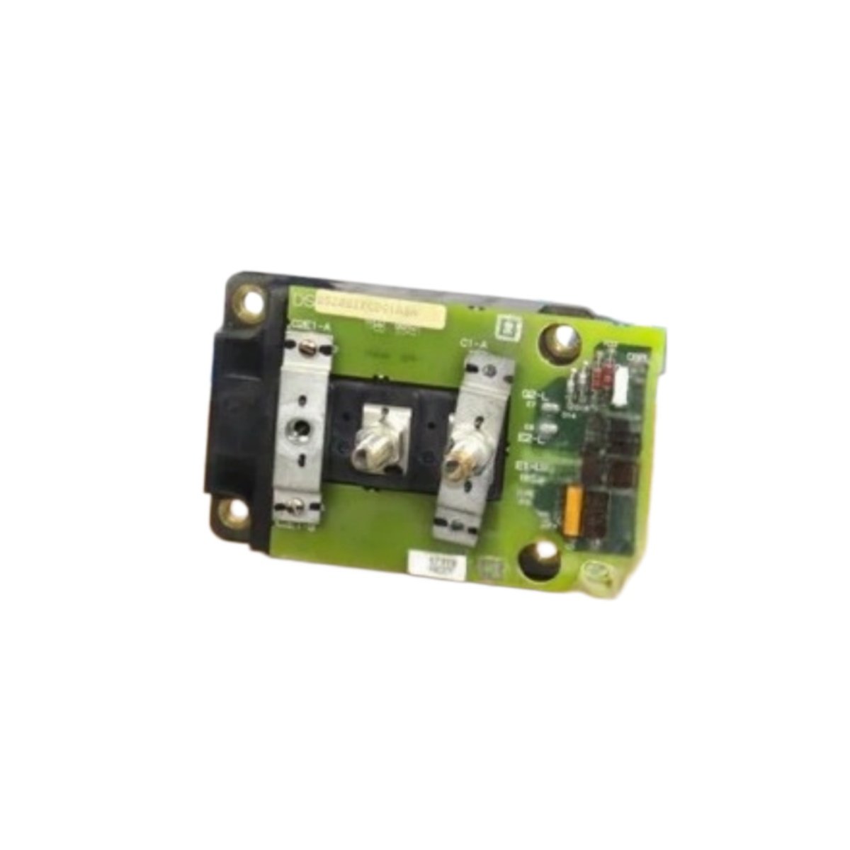
Voltage Spike Protection for AC2000 and EX2000 Drives
The GE DS200IPCDG1A DS200IPCDG1ABA suppresses voltage spikes in drive power circuits. This card protects IGBTs and SCRs from damaging overvoltage transients. It mounts directly across switching devices for maximum protection.
Technical Specifications
| Parameter | Specification |
|---|---|
| Model | DS200IPCDG1A DS200IPCDG1ABA |
| Category | Snubber Card |
| Height | 150 mm |
| Width | 80 mm |
| Depth | 25 mm |
| Weight | 0.280 kg |
| Snubber Type | RCD (resistor-capacitor-diode) |
| Capacitance | 0.47 µF per circuit (4 circuits total) |
| Capacitor Voltage Rating | 1200 V DC |
| Resistor Value | 10 Ω ±5%, 5 W |
| Resistor Type | Metal oxide (non-inductive) |
| Diode Type | Fast recovery (trr < 100 ns) |
| Diode Voltage Rating | 1200 V, 2 A |
| Number of Snubber Circuits | 4 independent |
| Peak Voltage Clamp | <950 V at 600 V bus |
| Connector Type | 2 x 8-pin headers |
| Status Indicators | None (passive device) |
| Internal Components | 4 capacitors, 4 resistors, 4 diodes, 1 PCB |
| Energy Storage | 0.47 µF per circuit (total 1.88 µF) |
Snubber Architecture and RCD Topology
The GE DS200IPCDG1A DS200IPCDG1ABA uses four independent RCD snubber circuits. Each circuit includes a capacitor, resistor, and fast recovery diode. The snubber connects directly across each IGBT or SCR device. It absorbs energy from parasitic inductances during switching transitions. The DS200IPCDG1A DS200IPCDG1ABA clamps voltage spikes below 950 V on a 600 V bus. This protection prevents device breakdown and extends component life.
Component Specifications and Ratings
Each snubber circuit contains a 0.47 µF capacitor rated at 1200 V DC. This capacitor absorbs turn-off energy without voltage breakdown. A 10 Ω, 5 watt metal oxide resistor dissipates the stored energy. The non-inductive resistor design prevents additional voltage spikes. A fast recovery diode with 100 ns reverse recovery time blocks reverse current. The GE DS200IPCDG1A DS200IPCDG1ABA uses through-hole components for high reliability.
Circuit Operation and Protection Mechanism
When the switching device turns off, the snubber capacitor charges through the diode. This action slows the voltage rise across the switching device. The resistor then discharges the capacitor before the next turn-off event. The DS200IPCDG1A DS200IPCDG1ABA repeats this cycle at the switching frequency. Typical switching frequencies range from 1 kHz to 20 kHz. The snubber card handles continuous operation without maintenance.
Physical Dimensions and Installation Guidelines
The GE DS200IPCDG1A DS200IPCDG1ABA weighs 0.280 kilograms for secure mounting. Its height measures 150mm, width 80mm, and depth 25mm. Install this card directly adjacent to the IGBT or SCR modules. Keep connecting leads as short as possible for maximum effectiveness. The card consumes no external power for its operation. It operates reliably from -20°C to +70°C ambient temperature.
Energy Storage and Discharge Characteristics
The DS200IPCDG1A DS200IPCDG1ABA stores energy in its 0.47 µF capacitors. Total capacitance across all four circuits equals 1.88 microfarads. Each capacitor stores energy according to the bus voltage squared. The resistors discharge the capacitors within 50 milliseconds typically. Wait 10 seconds before servicing the GE DS200IPCDG1A DS200IPCDG1ABA for safety. No battery is present on this passive snubber card.
Details
| Weight | 0.1 kg |
|---|---|
| Dimensions | 25 × 108 × 127 mm |
Reviews
There are no reviews yet.