The GE 531X304IBDANG1 functions as a high-performance digital input/output module within the Mark IV series, frequently paired with the F31X304IBDAMG1-006/09 version for enhanced flexibility. This module provides critical interfacing between field devices and the control system processor. It efficiently manages discrete signals from sensors, switches, and actuators throughout industrial applications.
Physical Characteristics and Build Quality
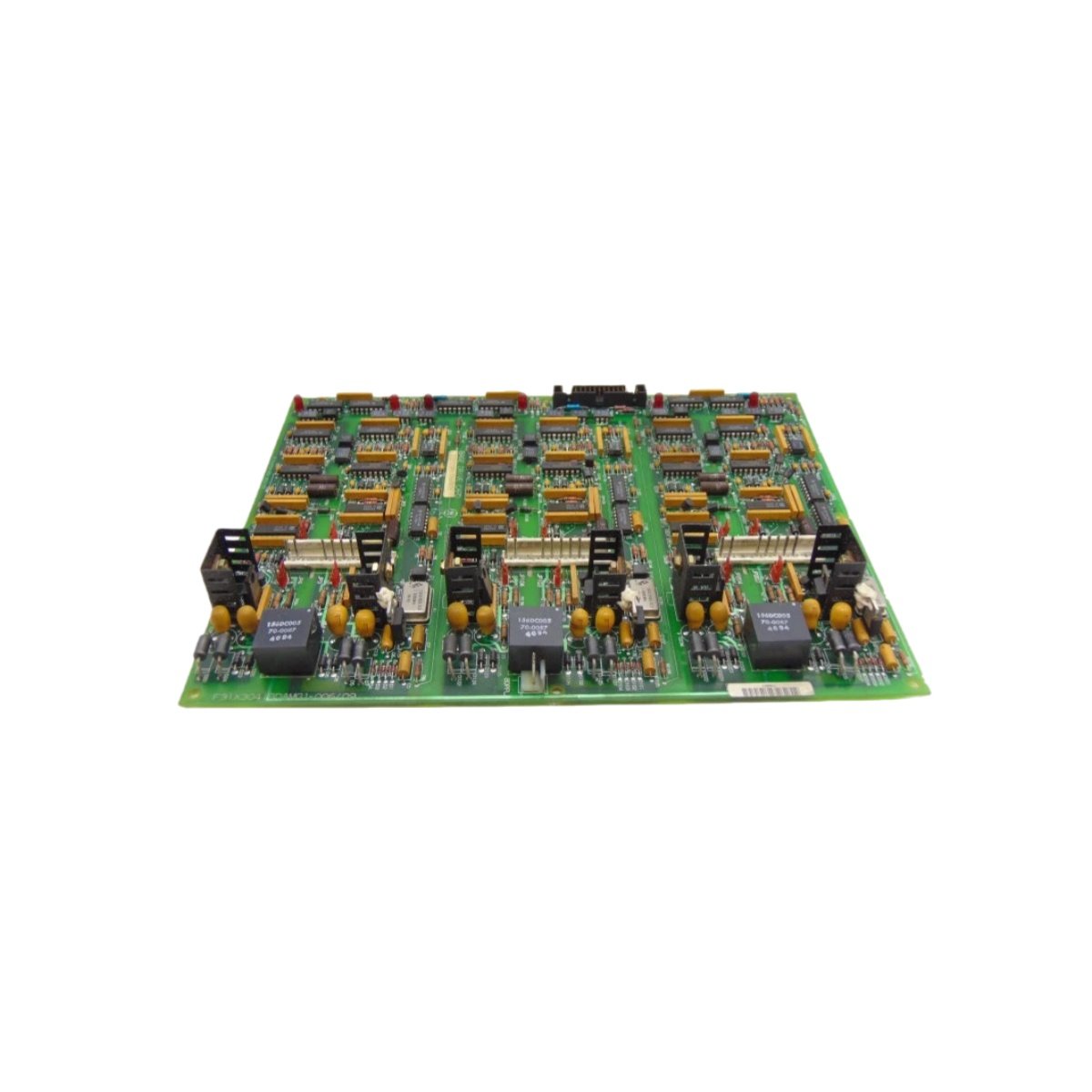
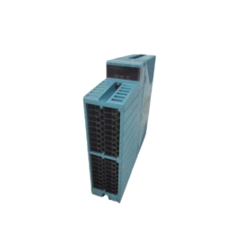
Engineers constructed this module using industrial-grade materials to withstand harsh environment conditions. The board measures approximately 25 centimeters in height and 18 centimeters in width, fitting standard rack mounting systems. Its total weight reaches roughly 0.9 kilograms, ensuring stable installation without excessive cabinet stress. The green solder mask and gold-plated edge connectors exemplify GE’s commitment to long-term reliability.
Technical Specifications
| Parameter | Specification |
|---|---|
| Module Dimensions | 25 cm (H) x 18 cm (W) x 3 cm (D) |
| Weight | 0.9 kg approximately |
| PCB Thickness | 1.6 mm industrial grade |
| Input Channels | 16 digital inputs, 24 VDC nominal |
| Output Channels | 16 digital outputs, 24 VDC sourcing |
| Connector Type | 50-pin ribbon cable header |
| Terminal Interface | Transition to screw terminals via cable |
| Component Count | 200+ ICs, transistors, resistors, capacitors |
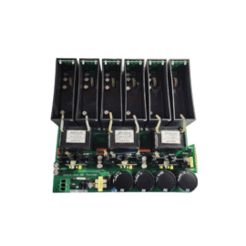
| Energy Storage | 470 µF filtering capacitors on power rails |
| Isolation | Optocoupler isolation per channel group |
| Power Requirements | 5 VDC logic, 24 VDC field supply |
| Operating Temperature | -20°C to +60°C |
| Status Indicators | LED per channel for input/output state |
Input Stage Design
The input circuitry accepts 24 VDC signals from field devices like proximity switches and pushbuttons. Each channel incorporates optocouplers for electrical isolation between field and logic sides. This design effectively prevents ground loops and protects the processor from voltage transients. Input filtering eliminates false triggering from electrical noise in industrial environments.
Output Stage Capabilities
Output channels source 24 VDC to control relays, solenoid valves, and indicator lamps. Each output includes short-circuit protection and thermal shutdown features. The 531X304IBDANG1 can switch up to 0.5 amps per channel continuously. Additionally, all outputs undergo rigorous testing to guarantee reliable operation under load.
Mark IV System Integration
This module mounts directly into the Mark IV control rack, connecting to the backplane for power and communication. The accompanying F31X304IBDAMG1-006/09 firmware configuration optimizes the module for specific application requirements. You can easily address each I/O point through the system’s software mapping tools. The board communicates with the main processor via the proprietary Genius bus protocol.
Diagnostic and Monitoring Features
Built-in diagnostics continuously monitor channel health and communication status. Green LEDs illuminate for each active input or output, providing immediate visual feedback. The module reports fault conditions directly to the controller for rapid operator response. This diagnostic capability significantly reduces troubleshooting time during maintenance activities.
Installation and Wiring Considerations
Proper installation requires careful attention to field wiring practices and shielding techniques. You should terminate all field wiring through the recommended transition panel for optimal performance. The module accepts wiring from 14 to 22 AWG conductors through the terminal interface. Always verify power supply polarity before inserting the module into the rack.
Details
| Weight | 0.1 kg |
|---|---|
| Dimensions | 25 × 108 × 127 mm |
Reviews
There are no reviews yet.