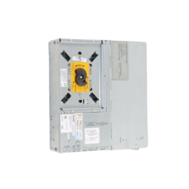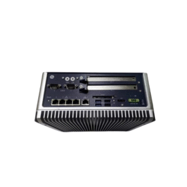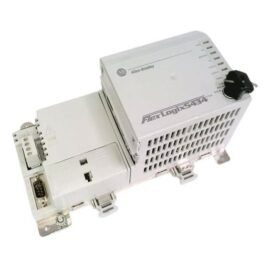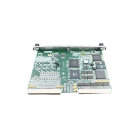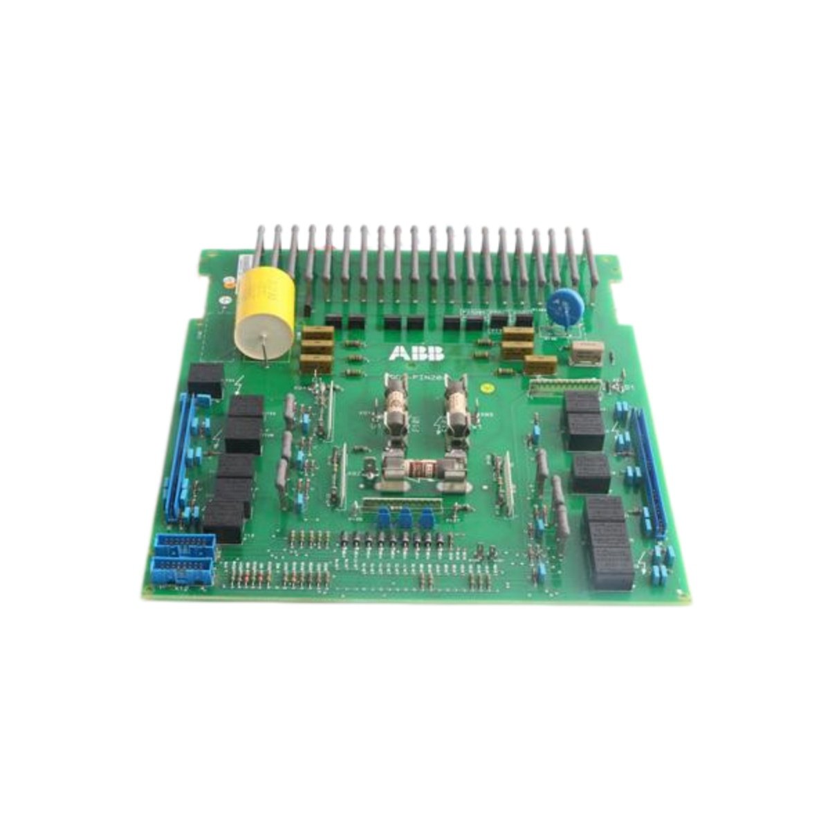
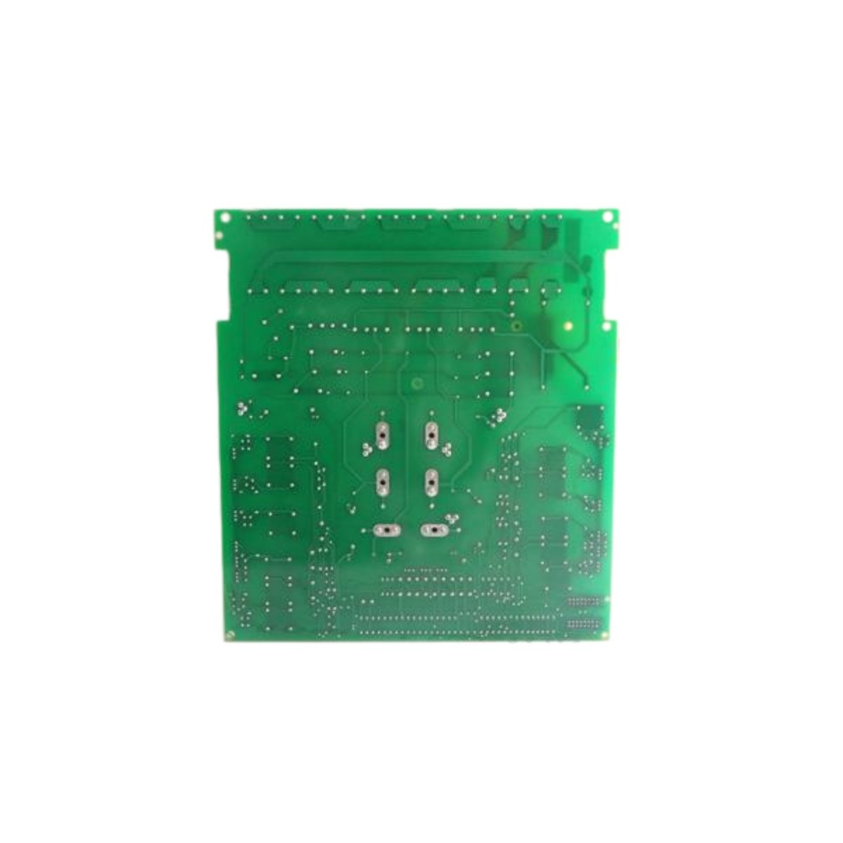
The ABB SDCS-PIN-205B DC drive power interface board manages power distribution between the supply and drive control circuits. This reliable module handles high-current switching and protection for demanding industrial drive applications. Its PCB measures 260 mm in length, 190 mm in width, and 35 mm in height.
Technical Specifications
| Parameter | Specification |
|---|---|
| Brand | ABB |
| Model | SDCS-PIN-205B |
| Category | DC Drive Power Interface Board |
| Rated Voltage | 400–690 V AC (input) |
| DC Link Voltage | 600–900 V DC |
| Continuous Current | 205 A |
| Peak Current (surge) | 350 A (10 ms) |
| Switching Frequency | 2.5 kHz |
| Power Dissipation | 85 W |
| Gate Drive Outputs | 6 channels (IGBT/MOSFET) |
| Digital Inputs | 4 channels (24 V DC) |
| Protection Features | Overcurrent, overvoltage, overtemperature |
| Internal Capacitance | 1,200 µF (DC link) |
| Dimensions (L×W×H) | 260 × 190 × 35 mm |
| Weight | 0.95 kg |
| Operating Temperature | –10°C to +50°C |
| Storage Temperature | –40°C to +70°C |
| Isolation Voltage | 2500 V AC (power-to-logic) |
| Component Count | 118 components |
Power Conversion and Switching Control
The ABB SDCS-PIN-205B converts incoming AC power to a regulated DC link voltage for the drive. Its 205 A continuous current capacity supports medium-to-large DC motor control applications. Six gate drive outputs provide switching signals for IGBTs or MOSFETs in the inverter section. The board manages switching at 2.5 kHz for balanced performance and efficiency.
Energy Storage and DC Link Management
A 1,200 µF capacitor bank stores energy to stabilize the DC link voltage. This capacitance ensures smooth current delivery during sudden load changes and transient events. The board monitors DC link voltage continuously and protects against overvoltage conditions. Such storage capacity reduces ripple and maintains power quality for consistent motor operation.
Protection Systems and Fault Handling
The ABB SDCS-PIN-205B incorporates comprehensive protection against overcurrent, overvoltage, and overtemperature events. An overcurrent trip activates at 205 A continuous and 350 A surge levels. The board includes a thermal sensor that shuts down the unit at 85°C. These protective measures safeguard the drive and connected motor from electrical or thermal damage.
I/O Interface and Status Monitoring
Four digital inputs accept 24 V DC signals from external interlock and safety devices. These inputs connect to emergency stop circuits, door switches, and thermal overload relays. LED indicators display power presence, fault status, and gate drive activity. Such visual feedback enables rapid diagnostics and troubleshooting during maintenance.
Signal Isolation and Noise Immunity
The board provides 2500 V AC isolation between the high-power section and control logic. This barrier protects sensitive microcontroller circuits from voltage spikes and transients. Optocouplers on the gate drive outputs ensure safe signal transmission across the isolation boundary. The design minimizes electromagnetic interference affecting nearby communication and measurement circuits.
Layout and Power Circuit Design
This PCB contains 118 components, including gate drivers, current sensors, and snubber capacitors. Heavy copper traces handle high currents while maintaining acceptable temperature rises. A thermal pad underneath the board conducts heat away to the mounting surface. Gold-plated terminals ensure reliable connections for the main AC supply and DC output conductors.
Installation and Mounting Specifications
Mount the ABB SDCS-PIN-205B vertically on a grounded metal backplate using four M5 screws. Maintain at least 50 mm clearance around the board for adequate airflow. Use appropriately sized cables for the AC input and DC output connections. The IP00 rating limits installation to enclosed electrical cabinets only.
Details
| Weight | 0.5 kg |
|---|---|
| Dimensions | 233 × 160 × 20 mm |