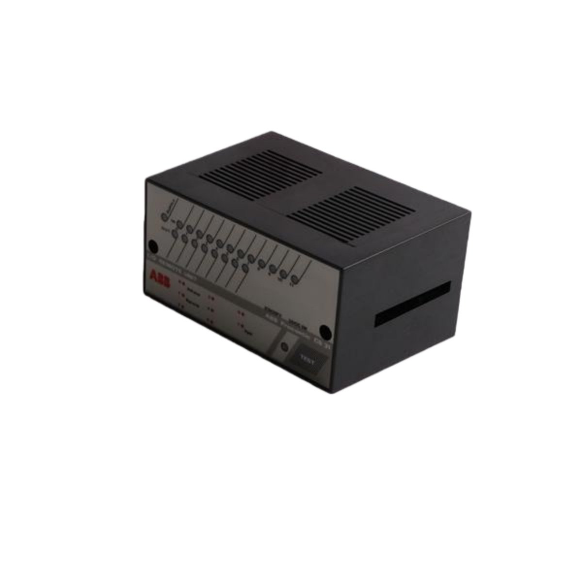
800xA Series Relay Output Control Module
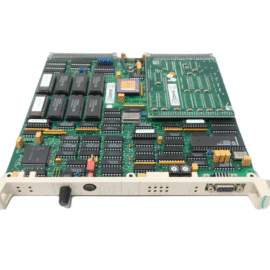
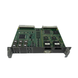
The PFUK108 YM110001-SH provides relay output control for the ABB 800xA distributed control system. This board drives external actuators, solenoids, and alarm devices through its multiple relay channels. It interfaces directly with the system backplane for command signals. The module also provides electrical isolation between the control logic and field circuits.
Key Technical Specifications
| Parameter | Specification |
|---|---|
| Brand | ABB |
| Model | PFUK108 YM110001-SH |
| Category | Relay Control Board |
| System Compatibility | 800xA Series DCS |
| Relay Channels | Offers 16 independent relay outputs |
| Contact Type | Features Form C (SPDT) contacts per channel |
| Contact Rating | Supports 5 A at 250 Vac or 30 Vdc |
| Power Supply | Draws +5 Vdc at 600 mA nominal |
| Coil Voltage | Operates on 24 Vdc relay coils |
| Isolation Voltage | Provides 1500 Vac isolation |
| Response Time | Delivers 10 ms typical switching speed |
| Mechanical Life | Rated for 10⁷ operations minimum |
| Electrical Life | Rated for 10⁵ operations at rated load |
| Operating Temperature | Functions from 0°C to +60°C |
| Storage Temperature | Withstands -40°C to +85°C |
| Dimensions | Measures 233.0 mm x 160.0 mm x 20.0 mm |
| Weight | Weighs approximately 0.6 kg |
| Mounting | Plugs into standard 800xA rack slots |
| Status LEDs | Displays POWER and individual channel states |
| Compliance | Meets CE, UL, and RoHS standards |
Relay Control and Switching Capabilities
This board controls up to sixteen independent field devices through its relay outputs. Each channel provides a Form C contact for flexible wiring configurations. The module also includes flyback diode protection for inductive loads. Moreover, it offers opto-isolation to protect the control circuitry from voltage spikes. The board’s fast response time ensures precise actuator control.
Installation and Configuration
First, insert the PFUK108 YM110001-SH into an available slot within the chassis. Ensure the board connects properly to the backplane interface. Next, wire the field devices to the relay terminal blocks. After that, apply power and confirm the LED indicators show normal status. You can then configure the relay logic through the system’s engineering software.
Maintenance and Operational Reliability
This board stores no user configuration data, relying on the system controller for logic. We recommend you test each relay channel periodically using the diagnostic functions. You should also inspect the terminal connections for any signs of overheating. The module’s high-contact rating ensures reliable operation in demanding industrial environments.
Details
| Weight | 0.6 kg |
|---|---|
| Dimensions | 233 × 160 × 20 mm |