800xA Series Signal Processing Core Module
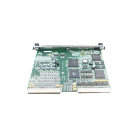
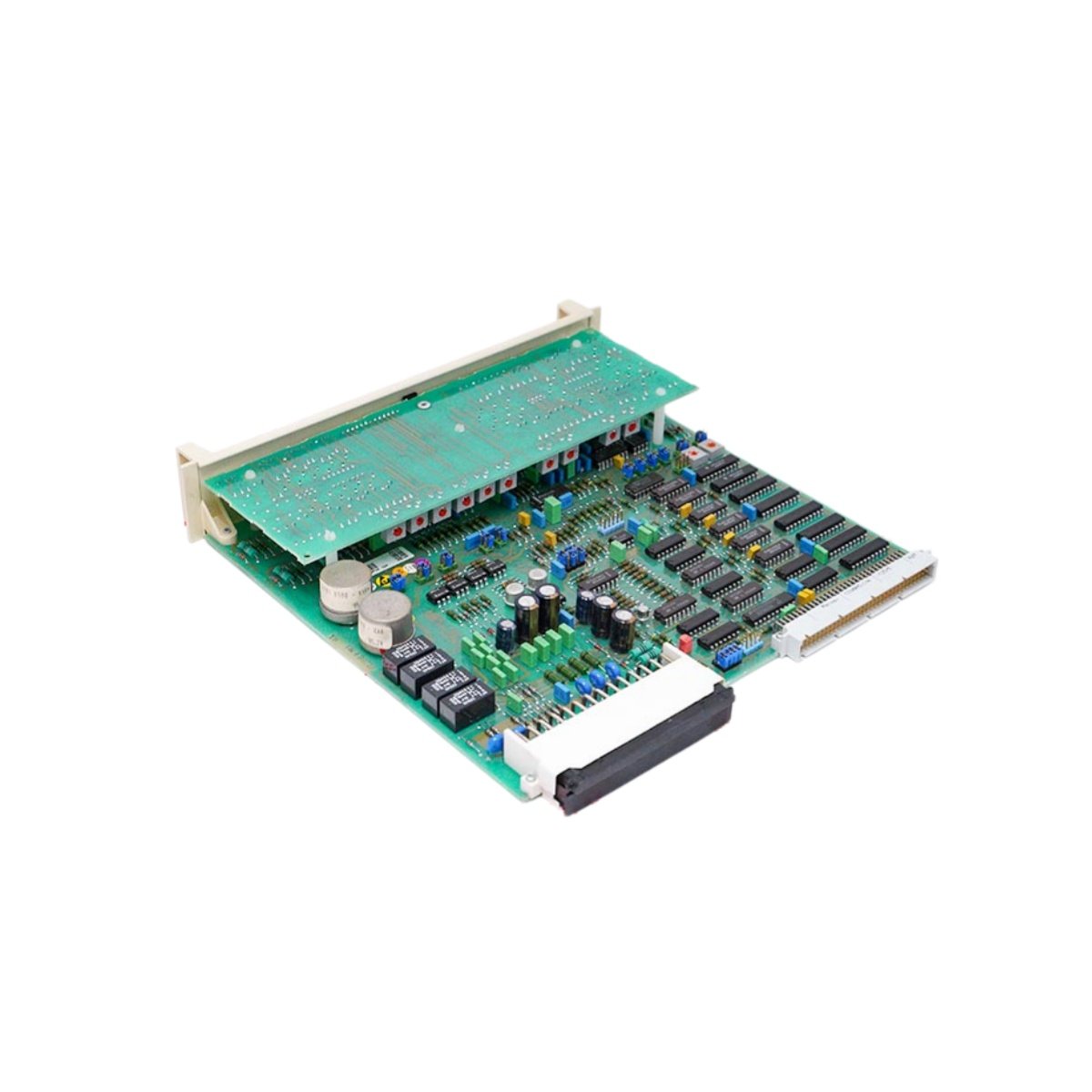
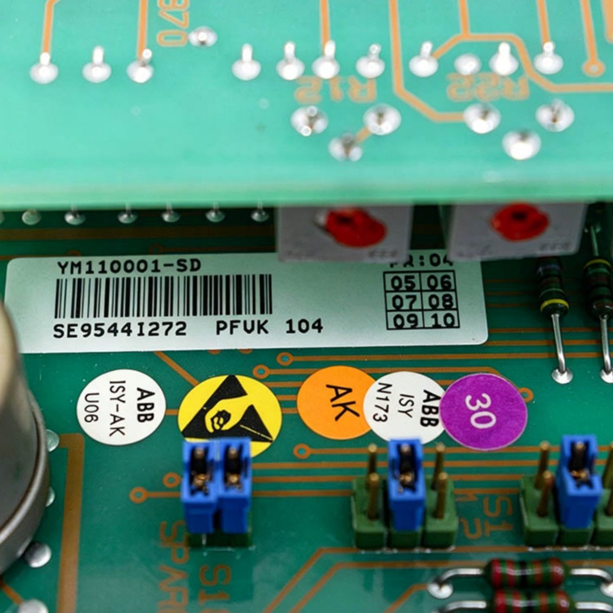
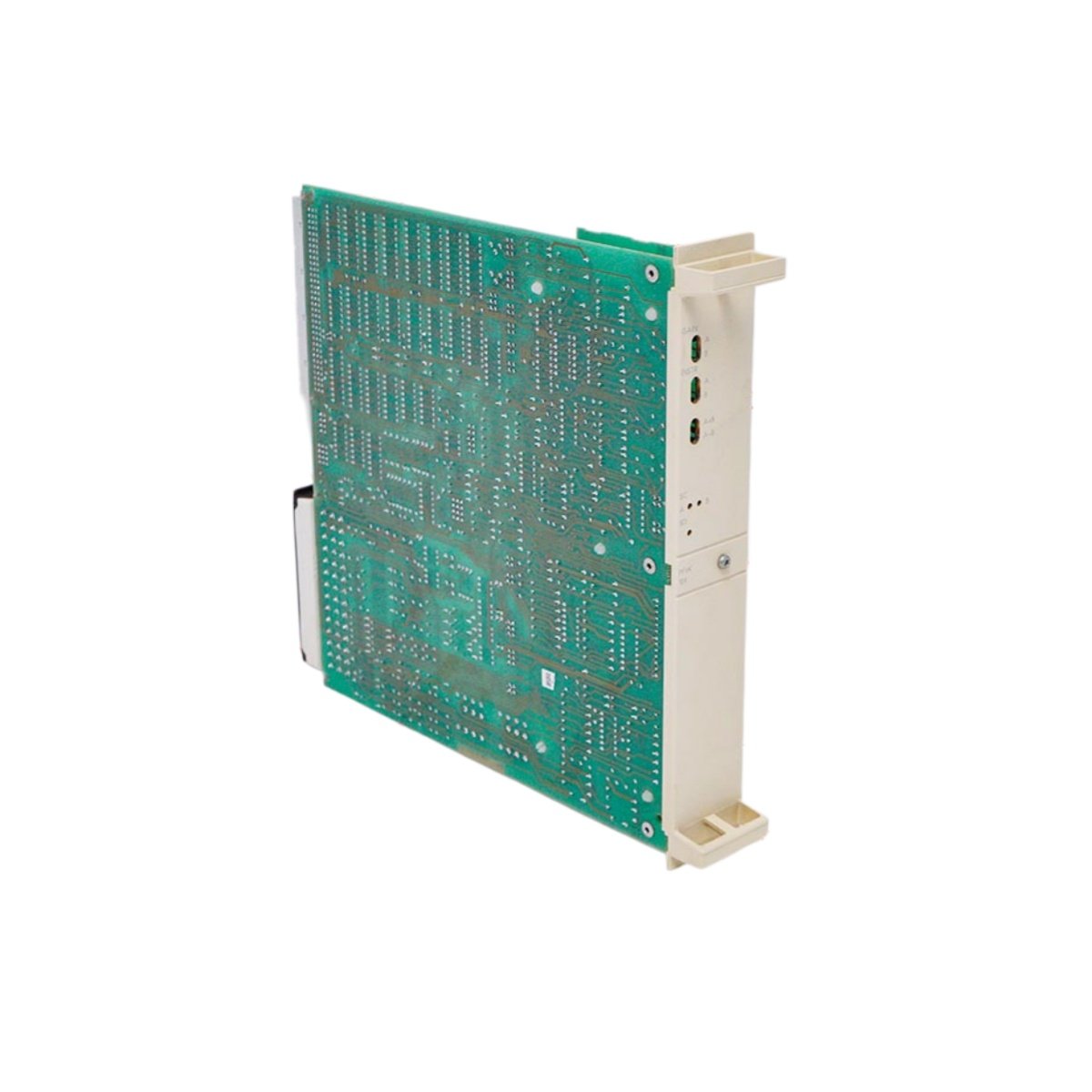
The PFUK104 YM110002-SD operates as a core signal processing board within the ABB 800xA architecture. This module handles complex signal conditioning and data conversion tasks. It interfaces with multiple field devices through its comprehensive I/O capabilities. The board also processes both analog and digital signals with high precision.
Key Technical Specifications
| Parameter | Specification |
|---|---|
| Brand | ABB |
| Model | PFUK104 YM110002-SD |
| Category | Core Signal Processing Board |
| System Compatibility | 800xA Series DCS |
| Processor | 32-bit RISC processor at 100 MHz |
| Memory | Includes 4 MB SRAM and 4 MB Flash |
| Power Supply | Draws +5 Vdc at 1.0 A maximum |
| Analog Inputs | Offers 8 differential channels |
| Analog Outputs | Provides 4 independent current outputs |
| Digital Inputs | Includes 16 optically isolated channels |
| Digital Outputs | Provides 8 relay contact outputs |
| Communication | Features two RS-485 serial ports |
| Resolution | Delivers 16-bit analog conversion |
| Operating Temperature | Functions from 0°C to +60°C |
| Storage Temperature | Withstands -40°C to +85°C |
| Dimensions | Measures 233.0 mm x 160.0 mm x 20.0 mm |
| Weight | Weighs approximately 0.55 kg |
| Mounting | Plugs into standard 800xA rack slots |
| Status LEDs | Displays POWER, RUN, ERROR, and COMM |
| Compliance | Meets CE, UL, and RoHS standards |
Signal Processing Capabilities
This core board performs high-speed analog-to-digital conversion on eight input channels. It also generates precise analog output signals for actuator control. The module processes digital input states and drives output relays accordingly. Moreover, it communicates processed data to the main controller via the serial ports. The board’s 16-bit resolution ensures accurate measurement and control.
Installation and Configuration
First, insert the PFUK104 YM110002-SD into an available rack slot. Ensure the board connects securely to the backplane interface. Next, wire the field signals to the designated terminal blocks. After that, apply power and confirm the LED indicators show normal status. You can then configure the signal scaling parameters using the engineering software.
Maintenance and System Reliability
This board stores its configuration data in non-volatile Flash memory. Therefore, a power cycle will not erase your programmed settings. We recommend you verify the analog input calibration periodically. You should also inspect the terminal connections for tightness during routine checks.
Details
| Weight | 0.55 kg |
|---|---|
| Dimensions | 233 × 160 × 20 mm |