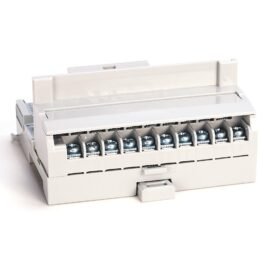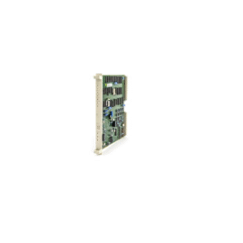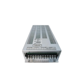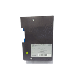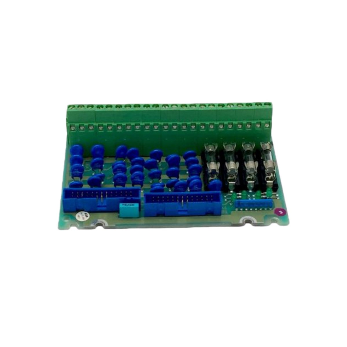
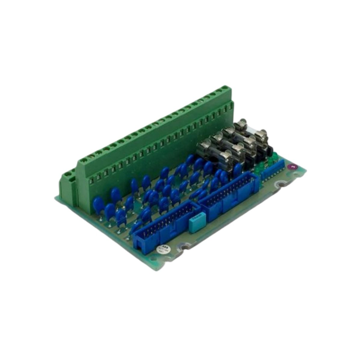
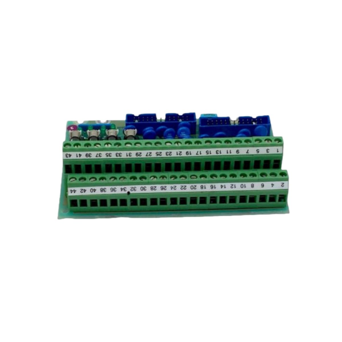
This connection unit provides centralized signal routing and distribution for industrial automation systems. It interconnects field devices with controller modules through organized terminal arrangements. The unit simplifies wiring complexity and reduces cabinet installation time.
Technical Specifications
| Parameter | Specification |
|---|---|
| Model Number | PFSK109 YM322001-EK |
| Product Type | Connection Unit / Signal Distribution Module |
| Supply Voltage | 24 V DC ±20% |
| Power Consumption | 5 W (maximum, excluding field loads) |
| Terminal Points | 48 x spring-clamp terminals |
| Signal Channels | 16 x configurable (analog or digital) |
| Max Voltage per Terminal | 250 V AC / 30 V DC |
| Max Current per Terminal | 10 A (continuous) |
| Bus Connection | 1 x 25-pin D-sub (for backplane interface) |
| Status Indicators | 8 x LED (channel-specific) |
| Grounding | Internal ground bus with dedicated terminal |
| Mounting | DIN rail (TS 35) |
| Dimensions (W x H x D) | 160 mm x 100 mm x 62 mm |
| Weight | 0.52 kg |
Mechanical Construction and Terminal Layout
This unit features a robust plastic housing with clearly numbered terminal positions. Its 160 mm width accommodates 48 spring-clamp connection points in two rows. The device weighs 0.52 kilograms and mounts securely on standard TS 35 DIN rails. All terminals accept wire gauges from 0.2 to 2.5 mm² for flexible cabling.
Power Distribution and Signal Routing
The module operates from a 24 V DC supply with generous tolerance. It consumes only 5 watts for internal logic and status monitoring. Sixteen configurable channels handle either analog or digital signals. An internal ground bus provides a common reference point for all connected devices. This unified grounding scheme minimizes noise and improves measurement accuracy.
Connectivity and Interface Options
A 25-pin D-sub connector links this unit to the main controller backplane. This interface carries both signal and power between connected modules. The terminal arrangement splits signals into clearly labeled input and output groups. Each channel includes a removable bridge for signal isolation during testing.
Diagnostic Features and Visual Indication
Eight front-panel LEDs display the status of critical signal channels. Each LED lights up when its corresponding channel receives an active signal. This visual feedback assists engineers during commissioning and fault finding. The unit also includes a test point for verifying the internal supply voltage.
Energy Storage and Transient Protection
Internal capacitors suppress voltage spikes and reduce electrical noise. These components also provide brief hold-up during minor supply dips. The unit incorporates varistor-based surge suppression for external transient protection. This safeguard prevents damage from lightning strikes or inductive load switching.
Installation and Maintenance Convenience
Spring-clamp terminals allow for tool-free wire insertion and secure retention. This termination method speeds up installation and reduces wiring errors. The hinged front cover protects terminals from accidental contact. Color-coded terminal blocks simplify identification of signal types at a glance.
Application Scenarios
This connection unit suits distributed I/O systems and marshalling cabinets. It works effectively in power plants, chemical facilities, and manufacturing lines. The device also supports building automation and infrastructure monitoring systems. Its operating temperature ranges from -20°C to +60°C.
Details
| Weight | 0.52 kg |
|---|---|
| Dimensions | 160 × 100 × 62 mm |