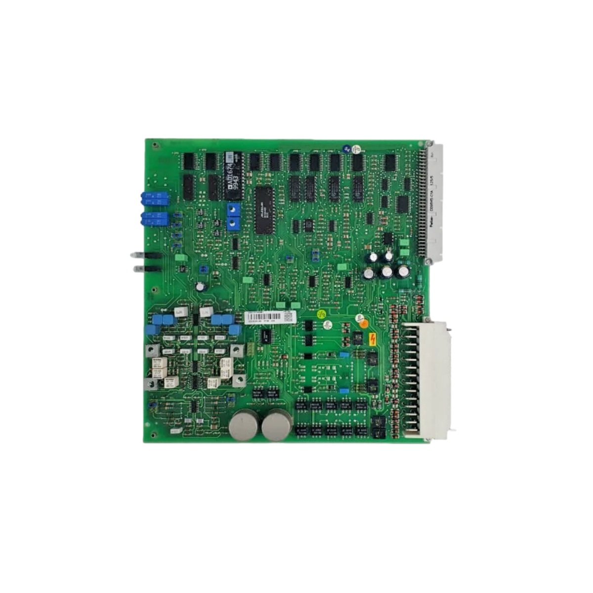
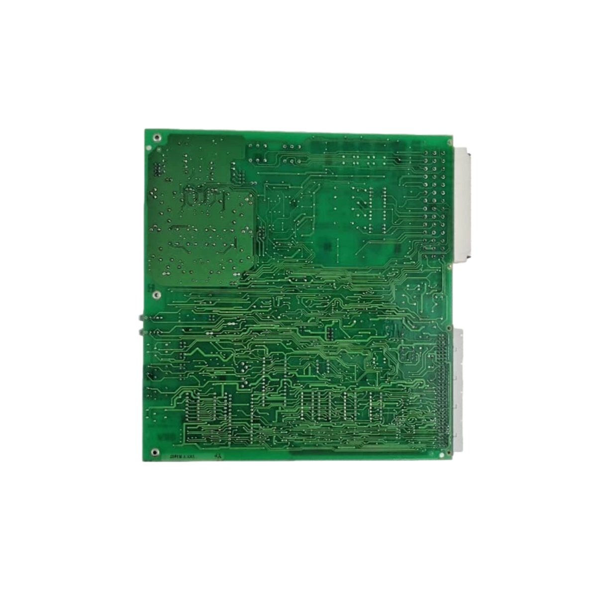
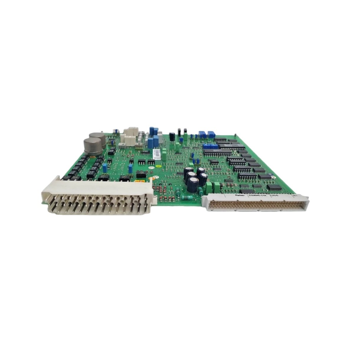
Signal Processing and Application Scope
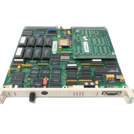
This high-reliability signal card provides robust signal conditioning for critical industrial processes. It supports multiple analog and digital signal types within a compact form factor. The card features eight universal input channels and four output channels for flexible configuration. Each channel includes galvanic isolation to eliminate ground loop interference. Consequently, this unit suits power generation, oil and gas, and chemical processing applications.
Technical Specifications
| Parameter | Specification |
|---|---|
| Brand | ABB |
| Model Number | PFBK164 3BSE000469R1 |
| Input Channels | 8 universal analog/digital inputs |
| Output Channels | 4 analog outputs (0–10 V / 4–20 mA) |
| Input Signal Types | 4–20 mA, 0–10 V, thermocouple, RTD |
| Output Signal Types | 4–20 mA or 0–10 V (software selectable) |
| Resolution | 16-bit ADC (inputs) / 14-bit DAC (outputs) |
| Accuracy | ±0.05% of full scale at 25°C |
| Temperature Drift | ±30 ppm/°C maximum |
| Isolation Type | Galvanic (channel-to-channel) |
| Isolation Voltage | 1500 VAC |
| Current Draw | 200 mA from 5 VDC backplane |
| Power Dissipation | 3.5 W typical / 4.5 W maximum |
| Operating Temperature | 0°C to +60°C |
| Storage Temperature | –40°C to +85°C |
| Humidity | 5% to 95% non-condensing |
| Dimensions (H x W x D) | 130 mm x 32 mm x 150 mm |
| Weight | 0.42 kg |
| Field Termination | 40-pin ribbon cable connector |
| Status Indicators | Channel health + power LED |
| MTBF | > 1,000,000 hours |
Input Versatility and Signal Conditioning
The PFBK164 3BSE000469R1 accepts a wide range of sensor inputs without external signal converters. It processes 4–20 mA current loops, 0–10 V voltage signals, thermocouples, and RTDs directly. Each input channel provides programmable gain and filtering for optimized measurement. A cold junction compensation circuit ensures accurate thermocouple readings. This versatility eliminates the need for additional signal conditioning modules.
Output Configuration and Control Capability
Four analog output channels provide 4–20 mA or 0–10 V signals for process control. Each output features a 14-bit DAC for smooth and precise signal generation. The card includes output short-circuit protection for fault tolerance. Users can configure each output independently through system software. This flexibility supports various field actuators and final control elements.
Wiring Interface and Termination Details
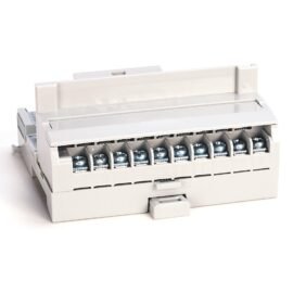
A 40-pin ribbon cable connects the signal card to field termination units. Each channel requires proper twisted-pair cabling for optimal noise immunity. The card provides dedicated terminals for shield connections on sensitive inputs. Maintain proper separation from high-voltage AC power cables. This wiring practice ensures accurate signal transmission in industrial environments.
Power Architecture and Energy Storage
This signal card draws 200 mA from the 5 VDC backplane supply. Internal capacitors store enough energy to bridge brief power interruptions. The card retains configuration parameters in non-volatile flash memory. Total power dissipation reaches 4.5 W under maximum operating load. This efficiency minimizes cabinet cooling requirements significantly.
Installation and Mounting Instructions
Insert the card into an available I/O chassis slot with the ejector tabs unlocked. Push firmly until the tabs engage securely in the locked position. Secure the card using the top and bottom retaining screws provided. Connect the field wiring harness after completing the mechanical installation. Observe the power LED to confirm correct energization.
Environmental Durability and Construction Quality
The PCB features conformal coating for protection against moisture and contaminants. Gold-plated connector contacts ensure reliable signal transmission over time. The card uses high-grade components selected for industrial longevity. This construction suits harsh environments with temperature fluctuations and vibration. The unit meets all relevant industrial safety and performance standards.
Diagnostics and Preventive Maintenance
LED indicators provide real-time status for each channel and overall card health. The system software offers comprehensive diagnostic data for troubleshooting. Replace the card if measurement accuracy exceeds specified tolerance limits. Perform periodic calibration verification using traceable reference standards. Maintain detailed calibration records for quality compliance.
Details
| Weight | 0.42 kg |
|---|---|
| Dimensions | 130 × 32 × 150 mm |