Module Function and Application Context
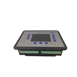
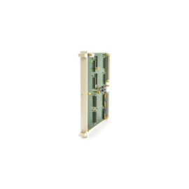
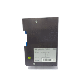
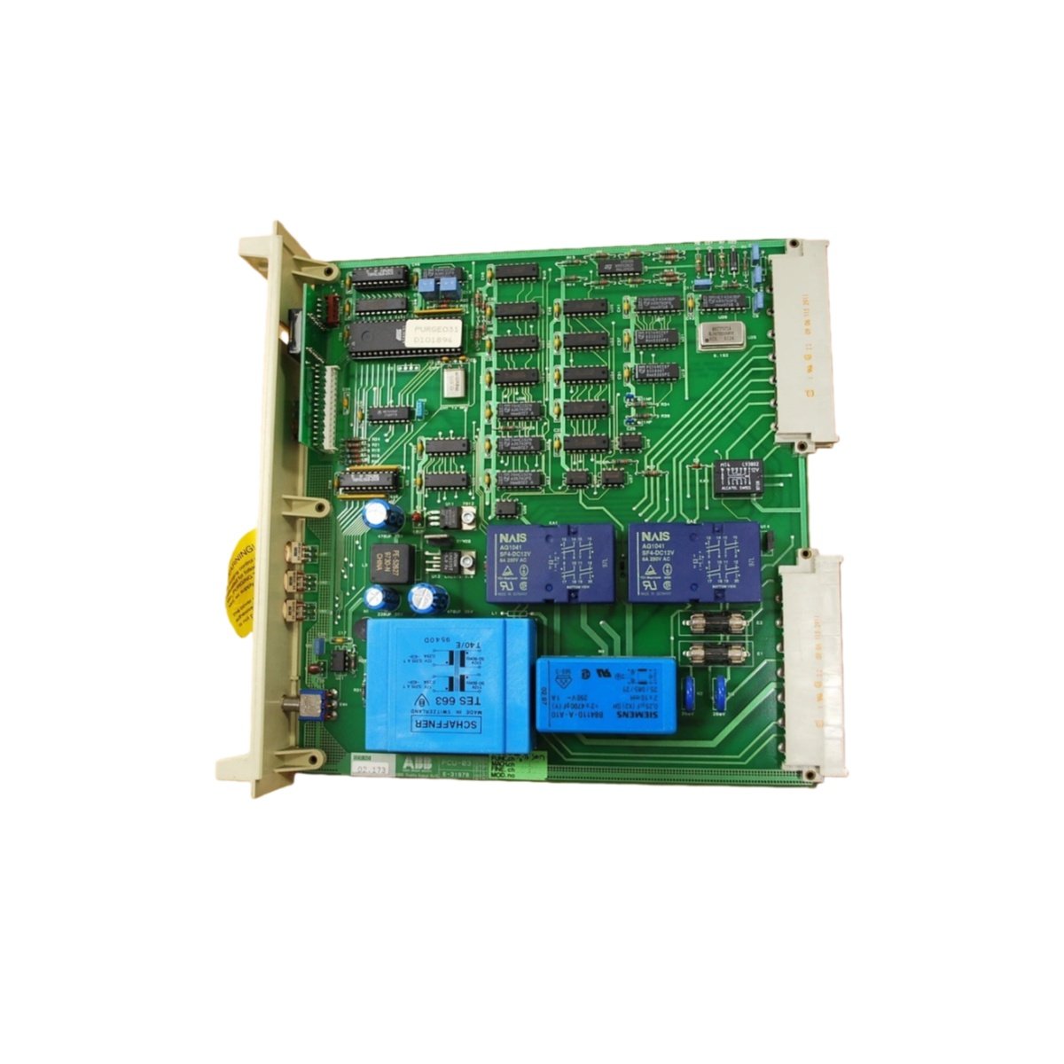
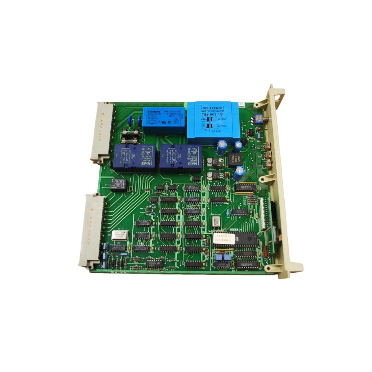
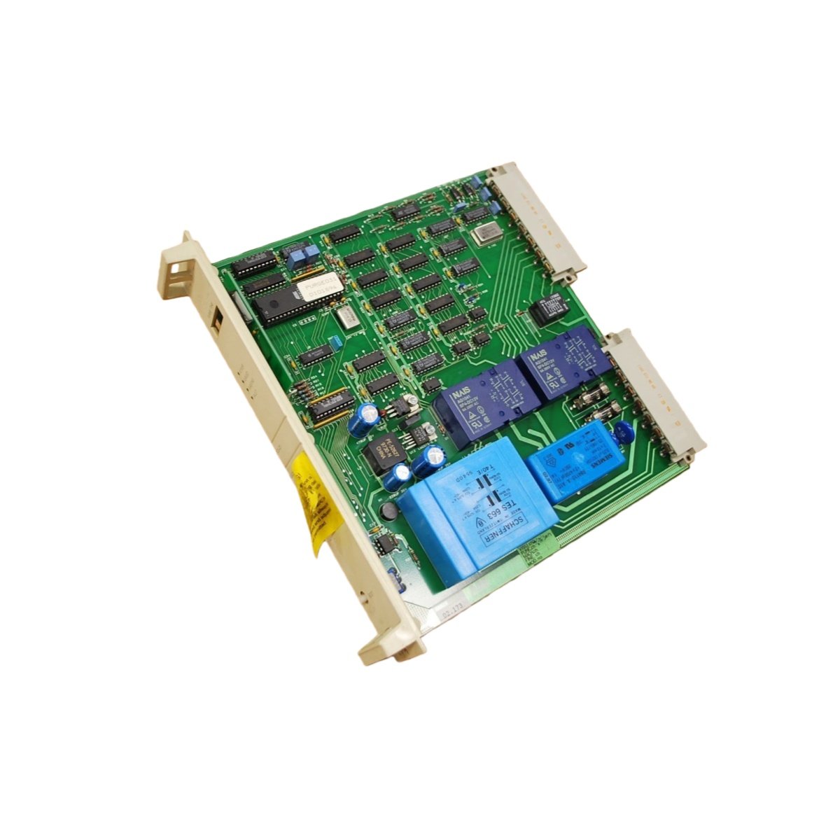
This purge controller module manages pressurization and purging sequences for hazardous area enclosures. It monitors pressure, flow, and purge time to ensure safe equipment operation. The module provides eight discrete inputs and four relay outputs for control functions. A dedicated termination interface simplifies field wiring connections. Consequently, this unit meets safety requirements for Zone 1 and Zone 2 classified areas.
Technical Specifications
| Parameter | Specification |
|---|---|
| Brand | ABB |
| Model Number | PCU-03 |
| Input Channels | 8 discrete digital inputs |
| Output Channels | 4 relay outputs (form C) |
| Input Voltage | 24 VDC nominal |
| Input Current | 10 mA per channel |
| Relay Contact Rating | 250 VAC / 30 VDC at 5 A |
| Relay Life | 100,000 operations minimum |
| Pressure Input Range | 0–10 bar (configurable) |
| Flow Input Range | 0–100 L/min (configurable) |
| Purge Timer Range | 1–600 seconds |
| Accuracy | ±1% of full scale |
| Isolation | 1500 VAC (input-to-output) |
| Operating Temperature | –20°C to +60°C |
| Storage Temperature | –40°C to +85°C |
| Humidity | 5% to 95% non-condensing |
| Dimensions (H x W x D) | 110 mm x 45 mm x 120 mm |
| Weight | 0.35 kg |
| Mounting | 35 mm DIN-rail |
| Termination | Screw-clamp terminals |
| Enclosure Rating | IP20 |
| Power Supply | 24 VDC external |
Purge Sequence Control and Safety Logic
The PCU-03 executes a programmed purge sequence upon receiving a start command. It monitors pressure buildup and flow rate throughout the entire cycle. The module verifies all safety interlocks before allowing equipment energization. A built-in timer tracks purge duration and compares it to the setpoint. Upon successful completion, it energizes the “safe to start” relay output.
Input Monitoring and Field Device Interface
Eight discrete inputs connect to pressure switches, flow sensors, and door interlock switches. Each input accepts 24 VDC signals from standard field devices. The module includes programmable debounce filtering for switch inputs. LED indicators display each input status for quick visual reference. This monitoring ensures the purge process only proceeds when all conditions permit.
Output Configuration and Relay Specifications
Four form-C relays provide output control for ventilation valves and alarm devices. Each relay handles up to 5 A at 250 VAC for direct actuator switching. The contacts feature gold-plating for reliable low-current signal switching. Users can configure each relay for normally open or normally closed operation. This flexibility accommodates various field equipment requirements.
Wiring Interface and Termination Details
Screw-clamp terminals accept solid or stranded wires from 14 to 22 AWG. Each input and output has clearly marked termination points for error-free wiring. The unit includes a dedicated earth terminal for proper grounding connections. Use shielded cables for pressure and flow sensor inputs. Proper shielding prevents electromagnetic interference from affecting measurements.
Power Requirements and Energy Buffering
The PCU-03 requires an external 24 VDC supply at 100 mA typical. Internal capacitors provide ride-through during brief supply interruptions. The module consumes 2.4 W under normal operating conditions. This low consumption reduces cabinet thermal load significantly. Ensure the power supply meets the required voltage and current specifications.
Construction Materials and Environmental Durability
The housing uses self-extinguishing polyamide for fire safety compliance. Terminal contacts feature corrosion-resistant nickel plating for long-term reliability. The PCB includes conformal coating for moisture and dust protection. This construction suits demanding industrial environments effectively. The unit meets IP20 standards for indoor installation.
Installation and Maintenance Guidelines
Mount the unit securely on a 35 mm DIN-rail using the integrated clips. Maintain adequate clearance for wiring access and heat dissipation. Strip wire ends to 7–8 mm for proper terminal insertion. Tighten each screw to 0.5–0.6 Nm for reliable connections. Test the purge sequence after installation to verify correct operation.
Details
| Weight | 0.35 kg |
|---|---|
| Dimensions | 110 × 45 × 120 mm |