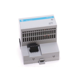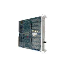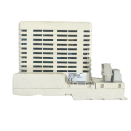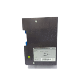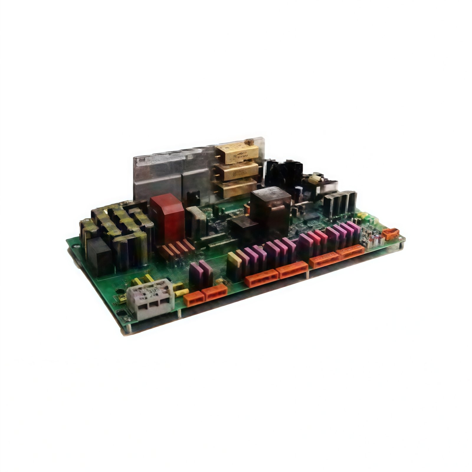
Output Architecture and Application Scope
This binary output module drives actuators, contactors, and alarm devices in industrial control systems. It provides 16 isolated output channels for robust field device control. Each channel delivers 24 VDC at 0.5 A continuously without derating. The module also includes individual short-circuit and overcurrent protection for every point. Therefore, this unit suits demanding applications requiring high output reliability.
Technical Specifications
| Parameter | Specification |
|---|---|
| Brand | ABB |
| Model Number | PAB02 P70870-4-0369059 369059A10 |
| Output Channels | 16 binary outputs |
| Output Voltage | 24 VDC nominal |
| Output Current | 0.5 A per channel (continuous) |
| Total Current | 8 A maximum (all channels) |
| Load Types | Resistive, inductive, capacitive |
| Protection | Short-circuit and overcurrent (per channel) |
| On-State Voltage Drop | <0.5 V at rated current |
| Off-State Leakage | <0.1 mA |
| Switching Speed | 1 ms typical |
| Isolation Type | Optical (channel-to-backplane) |
| Isolation Voltage | 1500 VAC |
| Logic Supply Current | 180 mA from 5 VDC backplane |
| Field Supply | External 24 VDC required |
| Power Dissipation | 5.5 W maximum |
| Operating Temperature | 0°C to +60°C |
| Storage Temperature | –40°C to +85°C |
| Dimensions (H x W x D) | 130 mm x 32 mm x 145 mm |
| Weight | Approximately 0.45 kg |
| Field Termination | 40-pin ribbon cable connector |
| Status Indicators | 16 red LEDs (per channel) + power |
Output Protection and Diagnostic Features
Each output channel incorporates automatic shutdown for overcurrent events. The module resets the affected channel after clearing the fault condition. A watchdog timer continuously monitors the communication link to the controller. This timer forces all outputs to a predefined safe state upon communication failure. Consequently, these protective measures safeguard both the module and connected field devices.
Field Wiring and Termination Interface
The PAB02 P70870-4-0369059 369059A10 terminates field wiring through a 40-pin connector. Each output channel provides two termination points for output and return. Connect inductive loads with external flyback diodes for voltage suppression. This practice protects the output transistors from damaging voltage spikes. Use shielded cables for optimal noise immunity in industrial environments.
Power Architecture and Energy Management
This module draws 180 mA from the 5 VDC logic supply through the backplane. The output power comes directly from an external 24 VDC field supply. Internal capacitors store sufficient energy to sustain outputs during brief interruptions. Total heat dissipation reaches 5.5 W under full load conditions. Ensure proper spacing between modules for effective cooling.
Installation and Mounting Procedure
Insert the module into any available Series T or compatible chassis slot. Press firmly until the ejector tabs engage securely in the locked position. Secure the module using the top and bottom retaining screws provided. Connect the field wiring harness after completing the mechanical installation. Verify the power LED illuminates after system energization.
Environmental Tolerance and Construction Quality
This module operates reliably in temperatures from 0°C to 60°C. It withstands humidity levels between 5% and 95% non-condensing. The PCB features conformal coating for protection against dust and moisture. This construction suits chemical plants and power generation facilities. Ensure adequate cabinet ventilation for sustained thermal performance.
Diagnostics and Routine Maintenance
Front-panel LEDs display each channel’s output status for quick visual verification. The system software provides detailed diagnostic data for troubleshooting purposes. Replace the module immediately if multiple outputs fail to activate correctly. Check the external 24 VDC supply if all outputs remain unresponsive. Keep a spare module available for emergency replacement scenarios.
Details
| Weight | 0.45 kg |
|---|---|
| Dimensions | 130 × 32 × 145 mm |