Termination Architecture and Channel Capacity
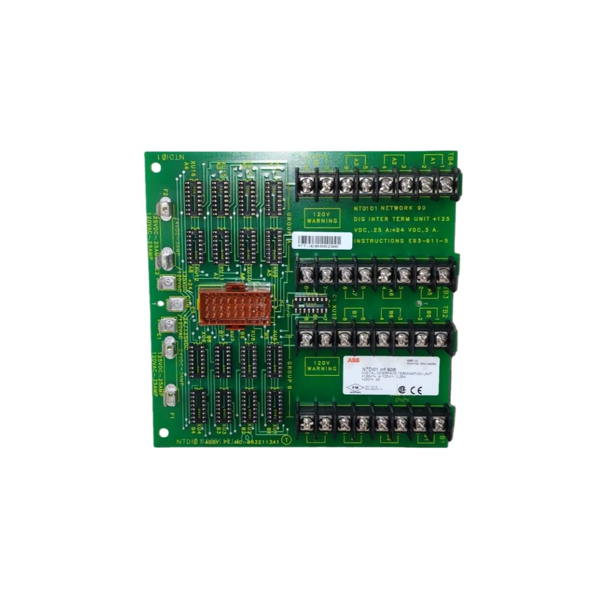
This digital I/O termination unit provides a centralized wiring interface for field devices and control systems. It supports up to 32 digital input or output channels in a single compact assembly. Each channel terminates individual field wires through reliable screw-clamp terminals. The unit also includes built-in fuse protection for every output channel. This design simplifies cabinet wiring and reduces installation labor significantly.
Technical Specifications
| Parameter | Specification |
|---|---|
| Brand | ABB |
| Model Number | NTDI01 |
| Channel Count | 32 digital I/O terminations |
| Termination Type | Screw-clamp terminals |
| Wire Gauge Range | 14–22 AWG |
| Fuse Protection | 2.5 A fast-acting per output channel |
| Rated Voltage | 250 VAC / 125 VDC |
| Rated Current | 2 A per channel (continuous) |
| Contact Material | Nickel-plated brass |
| Insulation Resistance | >100 MΩ at 500 VDC |
| Dielectric Strength | 2000 VAC for 1 minute |
| Operating Temperature | –25°C to +70°C |
| Storage Temperature | –40°C to +85°C |
| Dimensions (H x W x D) | 140 mm x 160 mm x 60 mm |
| Weight | Approximately 0.65 kg |
| Mounting | DIN-rail (35 mm) or panel |
| Connector Interface | 50-pin flat ribbon cable |
| Terminal Pitch | 5.08 mm |
| Marking | Label holder for channel identification |
Field Wiring and Termination Design
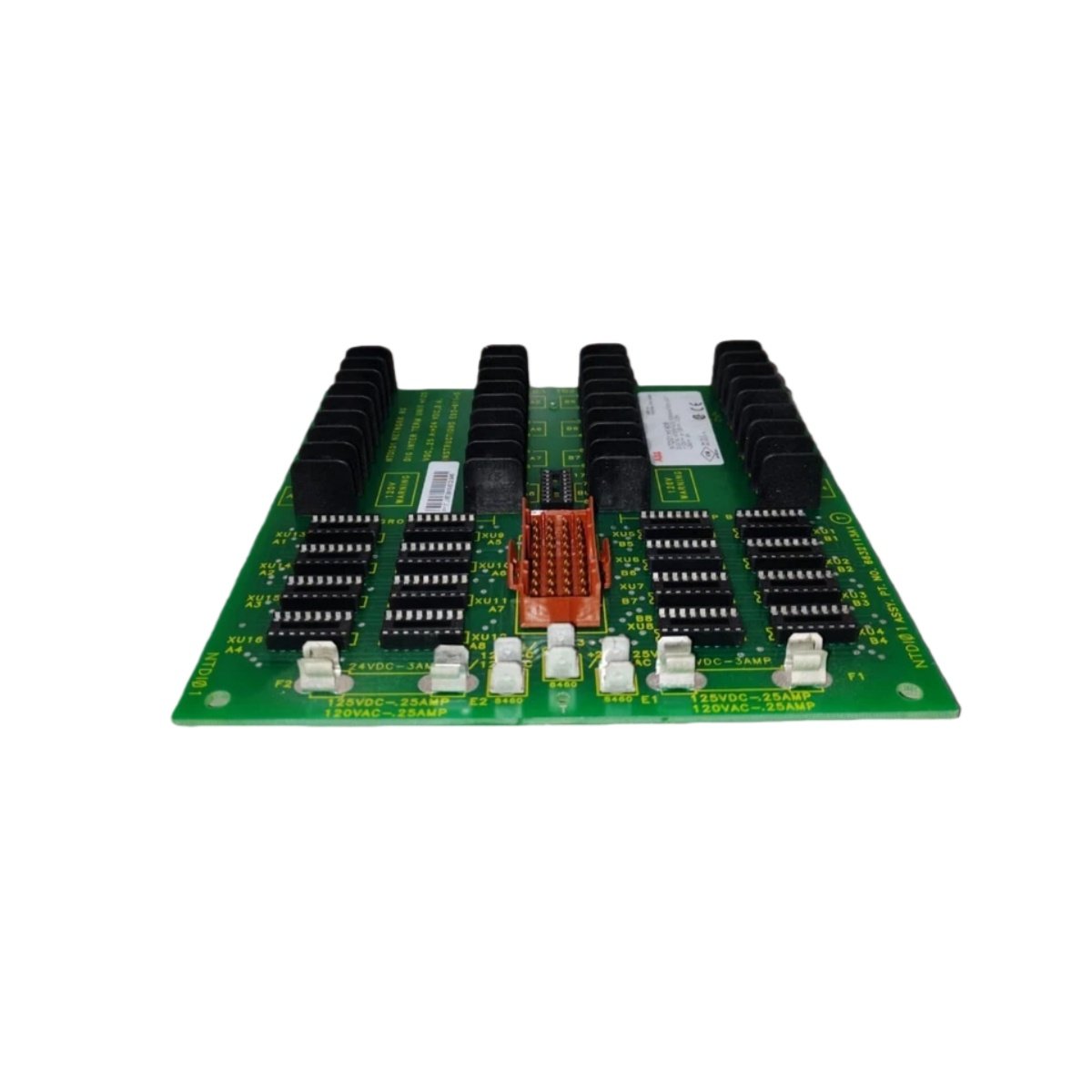
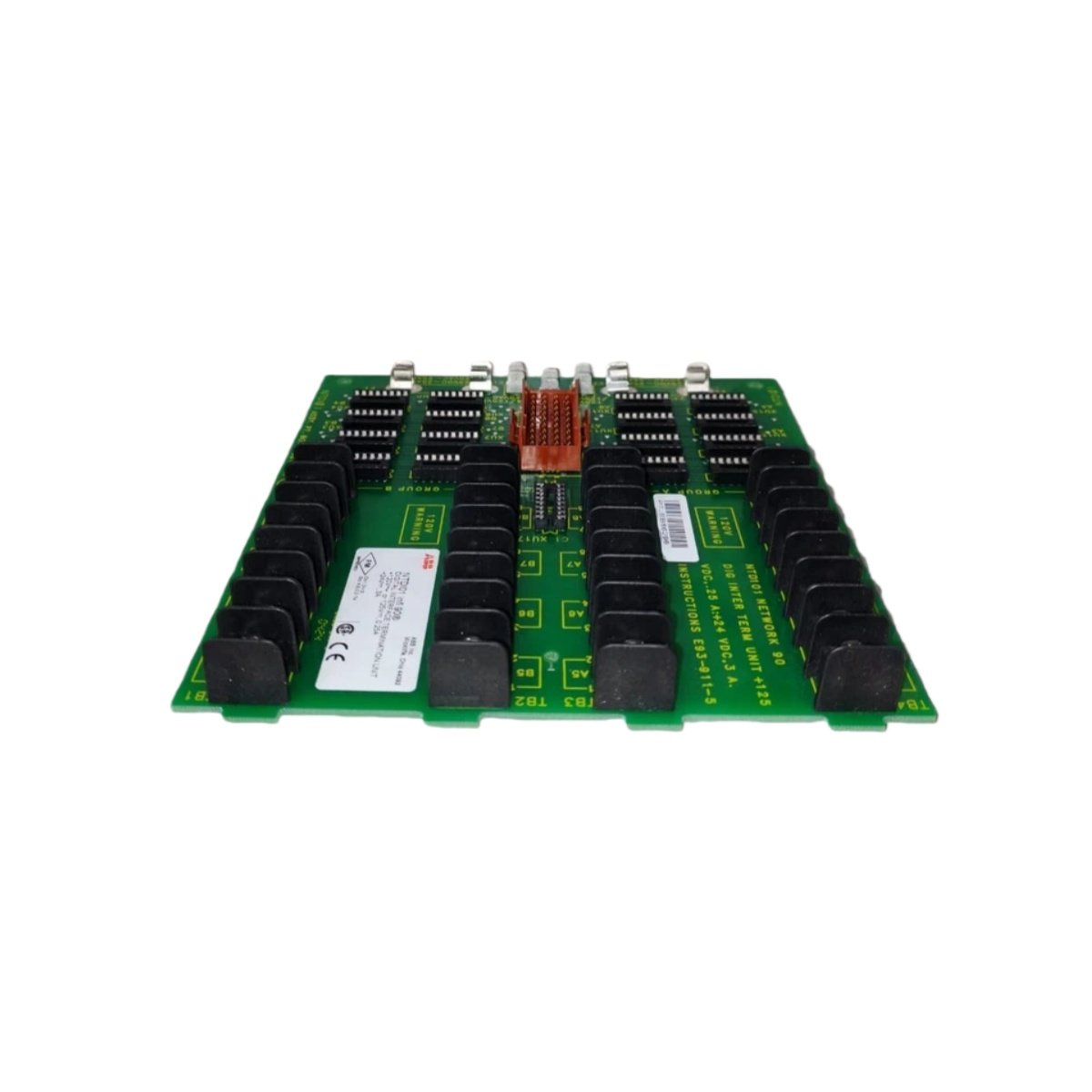
The NTDI01 uses screw-clamp terminals with a rising cage design for secure wire retention. Each channel provides two termination points: signal and common return. The unit includes a common ground bus bar for simplified field wiring. Integrated fuse holders protect each output channel from overcurrent conditions. This protection prevents damage to downstream control system components.
Signal Routing and Module Interface
This termination unit connects to ABB digital I/O modules via a 50-pin ribbon cable. The cable transmits all 32 signals simultaneously to the processing module. This single-cable approach dramatically reduces cabinet wiring complexity. The unit assigns each pin to a specific channel according to industry standards. Ensure the cable orientation matches the connector keying for correct signal routing.
Component Quality and Build Materials
The termination unit uses high-grade thermoplastic for the terminal housing. Brass contacts feature a nickel plating for excellent corrosion resistance. The PCB uses a glass-epoxy substrate for dimensional stability. Each unit undergoes factory testing for dielectric strength and insulation resistance. This quality assurance ensures reliable field service over many years.
Mounting and Installation Guidelines
Mount the unit securely on a standard 35 mm DIN rail using the integrated clips. Alternatively, fasten the unit to a cabinet panel using the mounting holes. Route field wiring through the cable entry points before termination. Label each channel clearly using the supplied marker strips. Verify all terminal screws achieve proper torque according to specifications.
Environmental Performance and Durability
This unit operates reliably across a –25°C to +70°C temperature range. It withstands 5% to 95% relative humidity without condensation issues. The housing provides protection against dust and accidental contact. This robust construction suits both indoor and sheltered outdoor installations. Ensure proper clearance for wiring access during maintenance.
Maintenance and Inspection Practices
Inspect all fuse holders periodically for signs of oxidation or damage. Replace blown fuses with the correct rating and type immediately. Check terminal screw tightness during routine maintenance rounds. Clean the unit gently using a soft brush or vacuum cleaner. Document any wiring changes for future troubleshooting reference.
Details
| Weight | 0.65 kg |
|---|---|
| Dimensions | 140 × 160 × 60 mm |