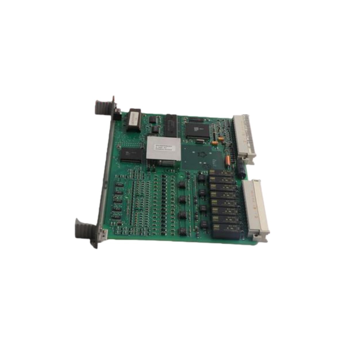
Termination Interface and Channel Organization
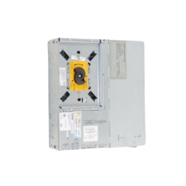
This digital input/output terminal unit offers a structured wiring interface for field devices. It accommodates up to 32 channels for both input and output applications. Each channel uses a screw-type terminal block for reliable wire connection. The unit also integrates fuse protection for every output point to prevent overcurrent damage. Furthermore, this design minimizes cabinet clutter and simplifies system troubleshooting.
Technical Specifications
| Parameter | Specification |
|---|---|
| Brand | ABB |
| Model Number | NTDI0-A |
| Channel Count | 32 digital I/O terminations |
| Termination Style | Rising cage screw terminals |
| Wire Gauge Capacity | 16–20 AWG |
| Output Fuse Rating | 2.5 A fast-acting per channel |
| Maximum Switching Voltage | 250 VAC / 125 VDC |
| Continuous Current | 2 A per terminal |
| Contact Resistance | <20 mΩ initial |
| Insulation Voltage | 2000 VAC for 1 minute |
| Insulation Resistance | >100 MΩ at 500 VDC |
| Terminal Pitch | 5.08 mm |
| Operating Temperature | –25°C to +70°C |
| Storage Temperature | –40°C to +85°C |
| Humidity Tolerance | 5% to 95% non-condensing |
| Dimensions (H x W x D) | 140 mm x 180 mm x 65 mm |
| Weight | 0.70 kg |
| Mounting Type | 35 mm DIN-rail or panel |
| System Interface | 50-pin flat ribbon connector |
| Labeling | Removable marker strips included |
Wiring Design and Connection Security
The NTDI0-A employs a rising cage clamp mechanism for each termination point. This design ensures consistent contact pressure and prevents wire loosening from vibration. Each channel includes clearly marked positive and negative terminals for error-free wiring. Additionally, the unit incorporates a common return bus bar for simplified ground connections. The terminal numbering aligns with standard ABB I/O mapping conventions.
Protection and Circuit Integrity
Each output channel features an individual fuse holder with a 2.5 A fast-acting fuse. This fuse protects the termination unit and the connected control module from short circuits. The fuse holders accept standard 5×20 mm cartridge fuses for easy replacement. Input channels include series resistors for current limiting. This protection scheme enhances overall system reliability and safety.
Signal Routing and System Integration
A 50-pin ribbon cable connects the NTDI0-A to ABB digital I/O processing modules. This single cable carries all 32 field signals to the control system. The connector uses polarization to prevent incorrect cable orientation. The unit assigns each pin to a specific channel according to the module pinout. Verify cable continuity before connecting to the processing module.
Construction Quality and Materials
The terminal housing consists of high-strength polyamide for excellent dimensional stability. The contact material uses copper alloy with a tin plating for oxidation resistance. The PCB employs FR-4 glass-epoxy laminate for reliable electrical insulation. All terminal screws receive nickel-chrome plating to prevent corrosion. This construction ensures reliable service in industrial environments.
Installation and Mounting Procedures
Mount the unit onto a 35 mm DIN-rail using the integrated spring clips. Alternatively, secure it to a backplate with the provided mounting holes. Allow adequate clearance above and below for wiring access. Strip wires to 7–8 mm for proper insertion into the terminals. Tighten each terminal screw to 0.5–0.6 Nm torque for secure retention.
Environmental Compatibility and Service Life
This unit operates effectively from –25°C to +70°C ambient temperatures. It withstands humidity levels between 5% and 95% without condensation. The housing resists common industrial chemicals and oils. Regular inspection of fuses and terminal tightness prolongs service life. Replace damaged terminals promptly to maintain signal integrity.
Details
| Weight | 0.70 kg |
|---|---|
| Dimensions | 140 × 180 × 65 mm |